Manuals
/
Acer
/
Computer Equipment
/
Computer Monitor
Acer
G195HQ
manual
Panel
Models:
G195HQ
1
32
55
55
Download
55 pages
46.78 Kb
29
30
31
32
33
34
35
36
Specifications
Install
Chart of G195HQ
Symbol Description
Connector Information
Disassembly Procedure
Screen Position Adjustment
Precautions
Volume Up / Down
Using the Right Power Cord
Page 32
Image 32
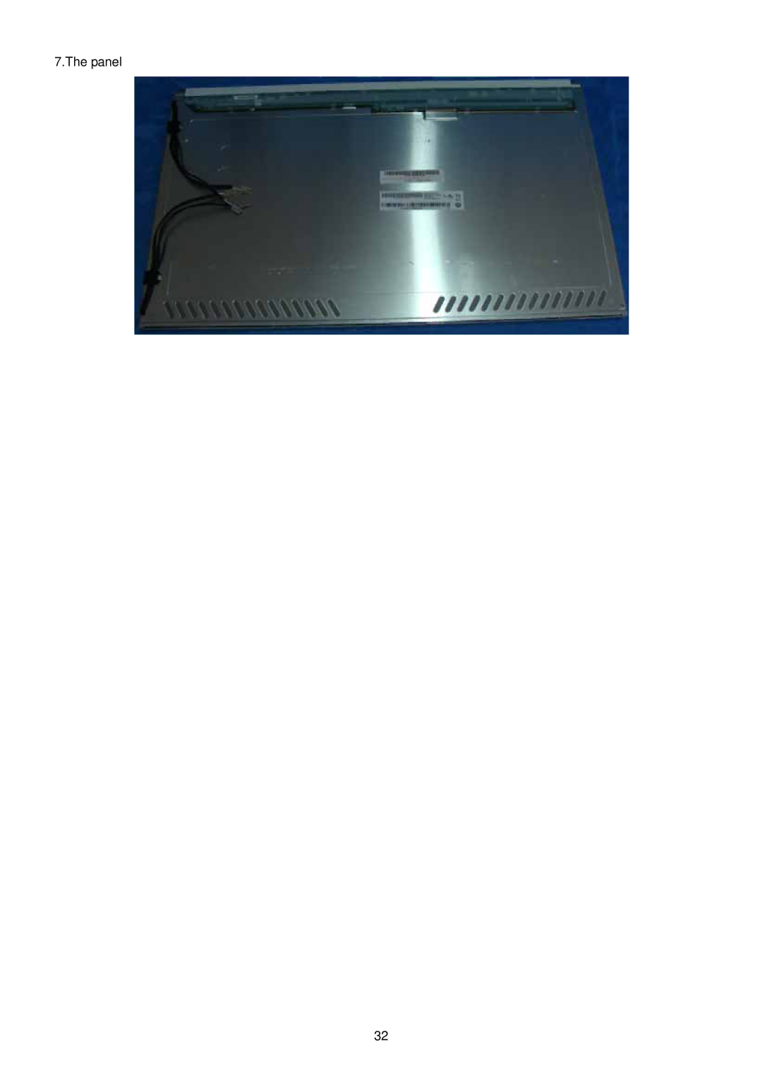
7.The panel
32
Page 31
Page 33
Page 32
Image 32
Page 31
Page 33
Contents
Acer G195HQ Service Guide
T89AM5D8MXAFN2
Service Guide Version and Revision
T89AM6D8MXAFH2
Copyright
Disclaimer
Trademarks
Conventions
Preface
Precautions
Special Notes on LCD Monitors
Table of Contents
Chart of G195HQ
Introduction
Scope
Description
Measurement systems
Electrical Requirements of G195HQ
Standard Test Conditions
EPA Energy Star
LCD Monitor General Specification
TTL
G195HQ
LCD Panel Specification of G195HQ
General Specifications
Optical Specifications
Factory Preset Timing of G195HQ
Monitor Block Diagram
Main Board Diagram
T89AM6D8MXAFH2 Dual-Input Model
DVI
RGB
ON/OFF DIM
Power Board Diagram
Mosfet
Software Flow Chart
Remark
715G2883 1
Symbol Description
Main Board Layout
Installation
Screen Position Adjustment
Attaching / Removing the Base
Volume Up / Down
User Controls
Adjusting the OSD settings
EColor Management OSD
Page
Page
Using the Right Power Cord
Tool for disassembly is as follows
Disassembly Procedure
Page
Page
Lvds Cable
Page
Panel
Main Board 1 No Power
Okng
No Picture LED is orange
Panel Power Circuit
OK NG
Key Board
Power Board
No power
No Backlight
Connector Information
Exploded Diagram Model G195HQ
FRU Field Replaceable Unit List Chapter
Description TPV Part No Acer Part No `ty
Part List
Picture Description TPV Part No Acer Part No
KEPC9QKO
Page
Main Board
DDC2SCL DDC2SDA
AO3401L
TSUM5PFHL
Lock type
DSUBB+
LVB0M RXO0
CBPC9M5AFQN
TSUM1PEL
Power board
Dbrt VIN
Key board
AUTO1K
Top
Page
Image
Contents