Manuals
/
Acer
/
Computer Equipment
/
Personal Computer
Acer
M3900
manual
Removing the TV Card
Models:
M3900
1
42
83
83
Download
83 pages
62.38 Kb
39
40
41
42
43
44
45
46
Troubleshooting
Block Diagram
Password
Load Default Settings
Cmos Setup Utility
Connector pin definition
System Bios
System Disassembly
Jumper Setting
Bios Recovery
Page 42
Image 42
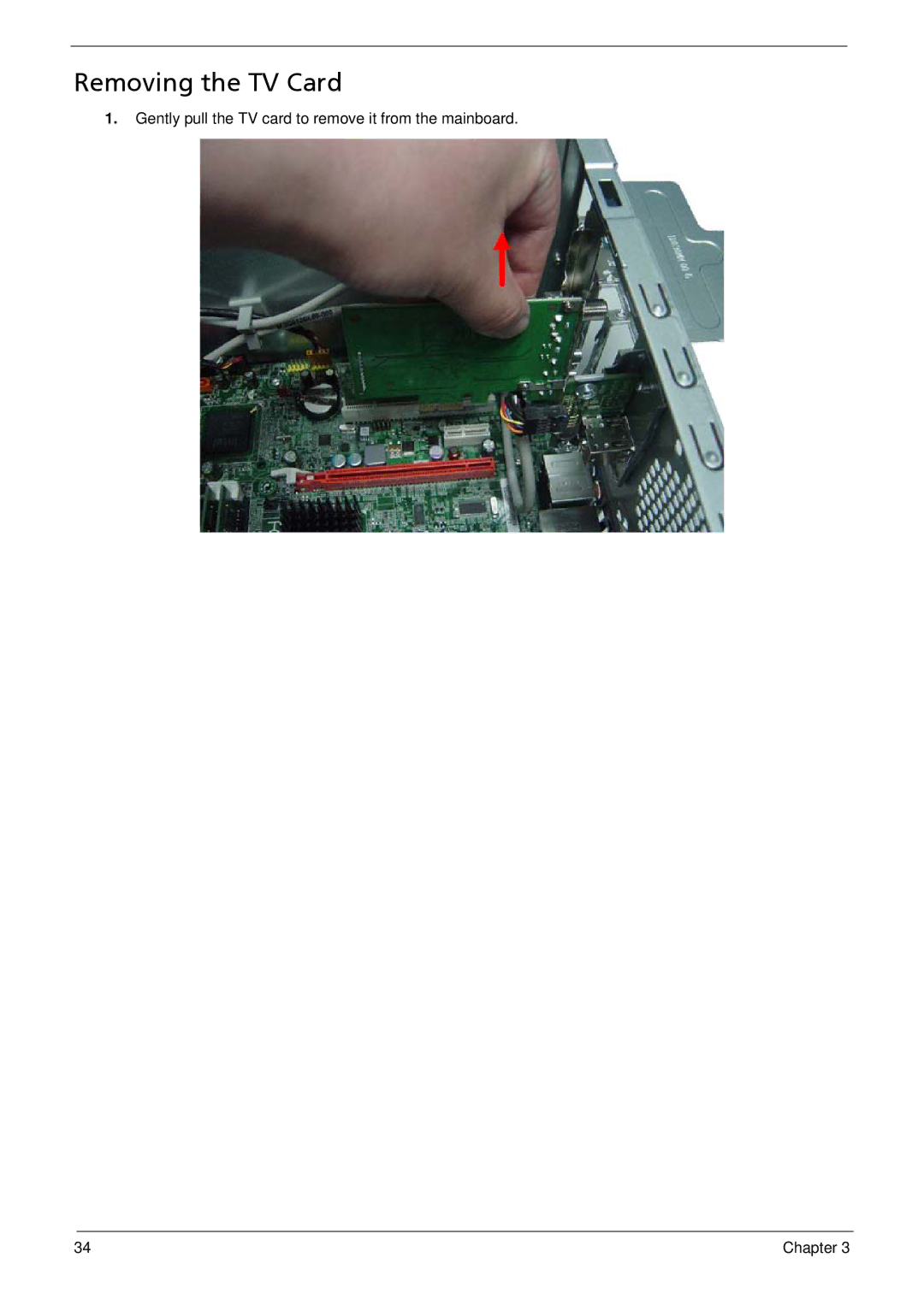
Removing the TV Card
1.
Gently pull the TV card to remove it from the mainboard.
34
Chapter 3
Page 41
Page 43
Page 42
Image 42
Page 41
Page 43
Contents
Acer Aspire M3900 Service Guide
Revision History
Copyright
Disclaimer
Conventions
Service Guide Coverage
Table of Contents
FRU Field Replaceable Unit List
Features
Chapter
Hard disk
On-Board Graphic solution
Audio
Optical disk
USB ports
Extension slot
Total I/O ports
System Bios
Power supply
Block Diagram
System Components
Front Panel
Rear Panel
Hardware Specifications and Configurations
IOS Hotkey List
Main Board Major Chips
Memory Combinations
System Memory
Audio Interface
USB Port
Power Management
Sata Interface
Environmental Requirements
Global Standby Mode
Power Management FunctionACPI support function
Device Standby Mode
Suspend Mode
Cmos Setup Utility
System Utilities
Entering Cmos setup
Navigating Through the Setup Utility
Setup Utility Menus
Parameter Description
Product Information
Standard Cmos Features
Parameter Description Option
Advanced Bios Feature
Enabled
Advanced Chipset Features
Integrated Peripherals
Power Management Setup
PC Health Status
Frequency/Voltage Control
Bios Security Features
Setting a supervisor password
Load Default Settings
Save & Exit Setup
Exit Without Saving
System Disassembly
Disassembly Requirements
Pre-disassembly Procedure
Removing the Side Panel
Removing the Heat Sink Fan Assembly
Page
Removing the Processor
Removing the VGA Card
Removing the TV Card
Removing the Mode Card
Removing the Memory Modules
Removing the Hard Disk Drive
Chapter
Removing the USB Board of Rear Panel
Chapter
Removing the Front Bezel
Pull the bezel away from the chassis
Removing the Optical Drive
Chapter
Removing the Removable HDD
Chapter
Page
Removing the Power Supply
Lift the power supply module out of the chassis Chapter
Removing the Card Reader
Pull the card reader out of chassis Chapter
Removing the Mainboard
Page
System Troubleshooting
Power System Check
System External Inspection
System Internal Inspection
Beep Codes
Viewing Bios checkpoints
Bootblock Initialization Code Checkpoints
Checkpoints
System is waking from Acpi S3 state
Bootblock Recovery Code Checkpoints
Checkpoint Description
Bios Recovery
Jumper and Connector Information
Placement
Label Description
Jumper Setting
Setting Jumper
Internal header pin definition
Front USB Header USBVCC1
Connector pin definition
Connector Name Function Definition
SATA1TXP SATA1TXN
ATX12V Conn
FRU Field Replaceable Unit List
Aspire M3900 Exploded DiagramAM350-ASSY
Aspire M3900 Exploded DiagramAM351-ASSY
Aspire M3900 FRU List
Components Model Name or Key Spec Acer P/N
CPU
VGA NV GT330 2GB DDR2 DVI+HDMI+VGA ATX Samsung
Geforce 310 512MB DDR2 Samsung 64BITS VGA DVI Hdmi
Components Model Name or Key Spec Acer P/N
Top
Page
Image
Contents