TravelMate
Service Guide
Revision History
Disclaimer
Copyright
Messages
Conventions
Preface
Table of Contents
Appendix C Online Support Information
Chapter FRU Field Replaceable Unit List
Chapter
Features
Audio
Page
Montara 855GME
System Block Diagram
Top View
Mainboard Placement
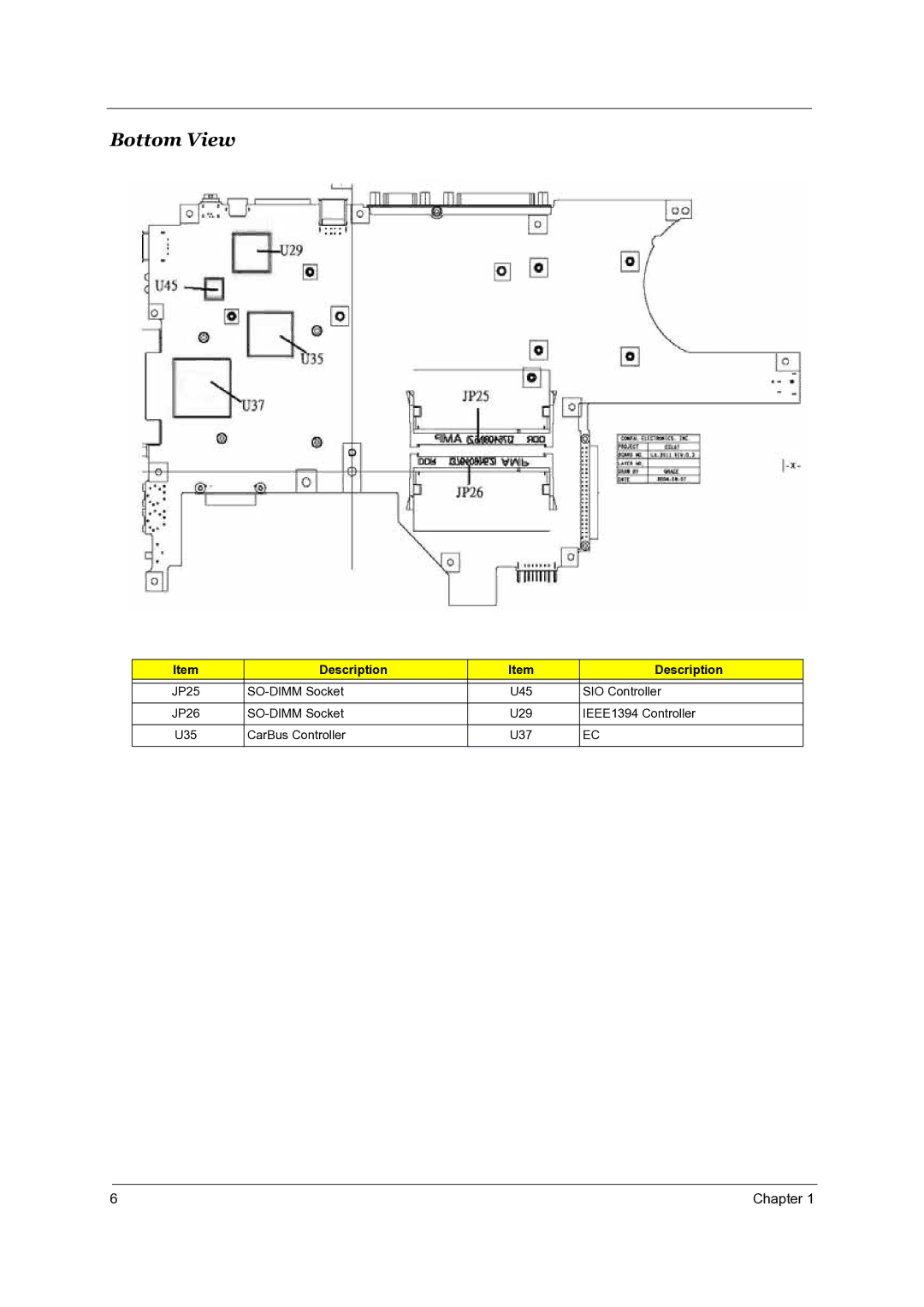
Description
Bottom View
Front Open View
Outlook View
Front View
Left View
HDD
Right View
Rear View
Bottom View
Icon Function Description
Indicators
ODD
Lock Key Description
Lock Keys
Embedded Numeric Keypad
Desired Access Num Lock On Num Lock Off
Key Description
Windows Keys
Hot Key Icon Function Description
Hot Keys
Click on Start, Settings, Control Panel
Euro Symbol
Launch Keys
Launch Key Default application
Touchpad Basics
Touchpad
Function Left Button Right Button Tap
Specification
Hardware Specifications and Configurations
1GB
0MB
Memory Combinations
2MB
MK3025GAS
ATA-5 ATA-6
Hlds GCC-4243N
IDE/ATAPI
QSI SDW-082S
Read
Lite-On SOSW-852S
Write
Recordable Media Type
Ohci
IRQ7, IRQ5
ICH4-M
UMA
855GHE/ICH4-M
14.0
TD141TGCD2
Delta ADP-65DB BG a 65W 3P
15.0
Power Management
Mechanical Specification
Navigating the Bios Utility
Bios Setup Utility
Hot Key Description
Parameter Description Device
Main
System
Parameter Description
Parameter Description Memory
Description Option
Advanced
DMA1, DMA2, DMA3
ASK IR, Fast IR
DMA1, DAM3
Bidirectional PS-2
May 20, 2003 54009 AM
Parameter Description Option
Security
Boot
Exit
Systemwillreboot
Bios Flash Utility
Machine Disassembly and Replacement
Before You Begin
General Information
Removing the Battery Pack
Removing the HDD Module
Removing HDD Module, ODD and Memory Module
Removing the ODD Module
Removing the Memory
Removing the Keyboard/LCD Module
Removing the Power Switch Board, Thermal and MDC
Removing the Keyboard
Removing the LCD module
Disassembling the Main Unit
Chapter
Page
Chapter
Disassembling the HDD Module
External Diskette Drive Check
System Check Procedures
External CD-ROM/DVD-ROM Drive Check
Keyboard or Auxiliary Input Device Check
Memory Check Power System Check
Check the Power Adapter
Display Check
Touchpad Check
Sound Check
Beep Code Message Description
Insyde MobilePro Bios Post Beep Code and Post Messages
No Interrupts from Timer
Parity Error AT Location
Boot Sector 0 has Changed
Rebooting
Symptom / Error Action in Sequence
Index of Symptom-to-FRU Error Message
LCD
Dimm
PCMCIA-Related Symptoms
LCD FPC
Peripheral-Related Symptoms
Dimm
Undetermined Problems
Top View
Jumper and Connector Locations
Bottom View
SW3 SettingsKill Switch
SW1 Settings Lid switch
Setting
FRU Field Replaceable Unit List
Exploded Diagram
Chapter
Picture Partname Description Part Number
Parts
Power Cord China
Power Cord Swiss
Power Cord Italian
Power Cord Demark
Thermal Cover
MDC+BLUETOOTH MDC+BLUETOOTH Combo Cover
MDC Cover
Combo Cover Plate W Plate W/ANTENNA Antenna
Module 24X QSI SBW QSI SBW-242C
DVD/CDRW Combo DVD/CDRW Combo Module
Module 24X Hlds GCC Hlds GCC-4243N
DVD Dual Module QSI DVD Dual Module QSI SDW-082
Keyboard
60.T70V5.005
Arabic Keyboard Belgium
Keyboard Zippy
Keyboard Brazilian
Portuguese Keyboard Canadian
N150X3-L07 W/WIRELESS Wireless Assy LCD Module 15
Wireless Assy LCD Module 15 Assy LCD Module 15 IN. AU
Sxga SAMSUNGLTN150P4-L03 W Wireless LCD 14.1 IN. XGA AU
Assy LCD Module Assy LCD Module 14.1 IN. XGA
LCD Panel with Logo
LCD Inverter
Antenna LCD Bezel 14
LCD Bezel -15
LCD Wire Cable 15 LCD Wire Cable 15 IN. XGA
LCD Wire Cable 14
LCD Bracket R 15
Pcmcia Slot
Thermal Module
Mainboard W/ Pcmcia Mainboard W/ Pcmcia SLOT, W/O
Touchpad Synaptics
Speaker R & L
TravelMate4050 G1&G2
Appendix a Model Definition and Configuration
Appendix B
Test Compatible Components
Model Vendor Description
Microsoft Windows XP / Professional Environment Test
1GB DDRI333
Hlds
Appendix C
Online Support Information