Main Unit Disassembly
External Modules Disassembly Flowchart
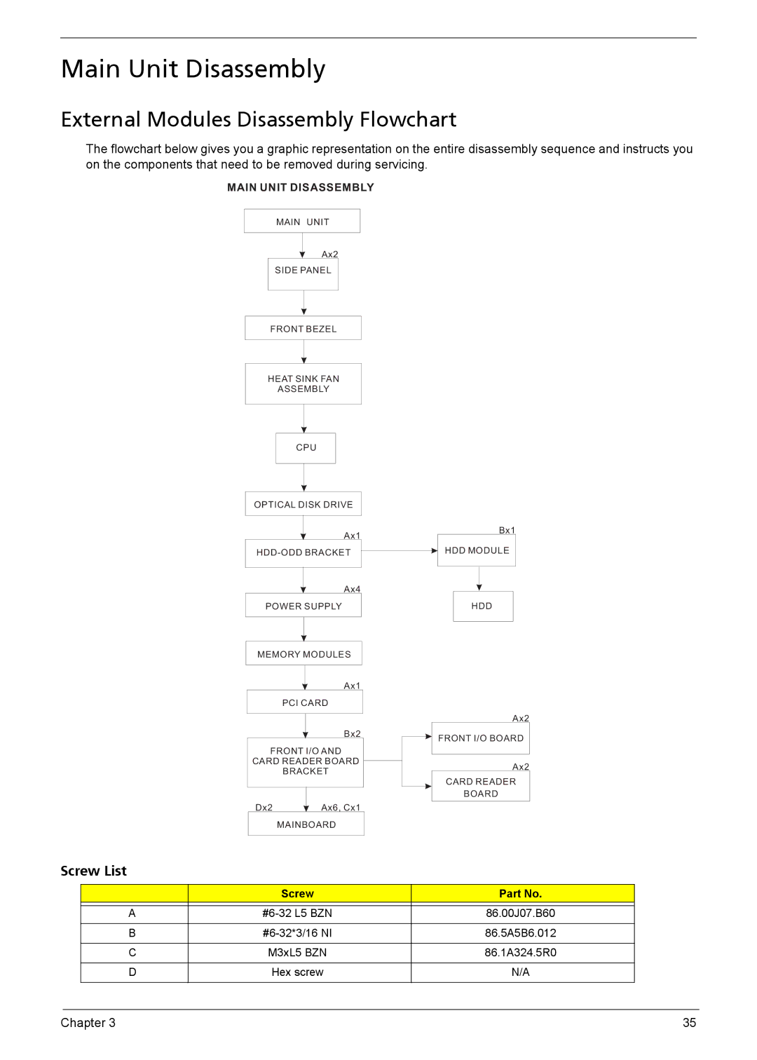
The flowchart below gives you a graphic representation on the entire disassembly sequence and instructs you on the components that need to be removed during servicing.
MAIN UNIT DISASSEMBLY
MAIN UNIT
Ax2
SIDE PANEL
FRONT BEZEL
HEAT SINK FAN
ASSEMBLY
CPU
OPTICAL DISK DRIVE
Ax1
Ax4
POWER SUPPLY
MEMORY MODULES
Ax1
PCI CARD
Bx2
FRONT I/O AND
CARD READER BOARD
BRACKET
Dx2 |
| Ax6, Cx1 |
|
MAINBOARD
Bx1
HDD MODULE
HDD
Ax2
FRONT I/O BOARD
Ax2
CARD READER
BOARD
Screw List
| Screw | Part No. |
|
|
|
A | 86.00J07.B60 | |
|
|
|
B | 86.5A5B6.012 | |
|
|
|
C | M3xL5 BZN | 86.1A324.5R0 |
|
|
|
D | Hex screw | N/A |
|
|
|
Chapter 3 | 35 |