Rear Panel Function and Operation
|
|
|
|
|
|
| 17 |
|
| 16 |
| 15 | 14 |
| 13 12 11 10 |
| |||
| CAUTION | cesonic | MIXING AMPLIFIER |
| BGM |
|
|
|
|
|
|
|
|
|
|
|
|
| |
| RISK OF ELECTRIC |
|
|
|
|
|
|
|
|
|
|
|
|
|
| ||||
| SHOCK DO NOT OPEN |
| INPUT |
|
|
|
|
|
|
| S.VIDEO |
|
|
|
|
| |||
| WARNING:TO REDUCE THE RISK OF FIRE OR ELECTRIC SHOCK | S/N |
|
|
| DVD |
|
|
|
|
|
|
| INPUT |
|
|
|
|
|
| DO NOT EXPOSE THIS APPLIANCE TO RAIN OR MOISTORE | CITYOF INDUSTRY,CA,USA |
|
|
| Cr | Cb | Y |
|
|
|
|
|
|
| ||||
|
|
| INPUT |
|
| INPUT/OUTPUT | VIDEO | S.VIDEO |
|
|
|
|
| ||||||
|
|
| acesonic.com |
|
|
|
|
|
| BGM | AUX | DVD | VIDEO OUT | ||||||
|
|
|
|
|
|
|
|
|
| PC USB |
|
| |||||||
|
|
|
|
|
| Cr | Cb | Y | COMPONENT OUTPUT | PC INPUT |
|
|
|
|
| ||||
|
|
|
|
|
|
|
|
|
|
|
|
|
| VIDEO |
|
|
|
|
|
|
|
|
|
|
|
|
|
|
|
|
|
|
| INPUT |
|
|
|
|
|
|
|
|
| UNLOCK |
|
| UNLOCK |
|
|
|
|
|
|
|
|
|
|
|
|
| VOLTAGE SELECT |
|
|
|
|
|
|
|
|
|
|
|
| L |
|
|
|
|
|
|
|
|
|
|
|
|
|
|
|
|
|
|
|
|
|
|
|
| |
1 |
| A |
|
|
| LOCK |
|
| LOCK | A |
|
|
| AUDIO |
|
|
|
|
|
115V |
|
|
|
|
|
|
|
|
|
| INPUT |
|
|
|
|
| |||
|
|
|
|
|
|
|
|
|
|
|
|
| R |
|
|
|
|
| |
|
|
|
|
|
|
|
|
|
|
|
|
|
|
|
|
|
|
| |
|
|
|
| RIGHT |
|
| LEFT |
|
|
|
|
|
|
| BGM | AUX | DVD | AUDIO OUT | |
| AC INPUT |
|
|
|
|
|
|
|
|
|
|
|
|
|
|
|
|
|
|
| ~230/115V 50/60Hz |
|
|
|
|
|
|
|
|
|
|
|
|
| OUTPUT |
| PRE | ||
|
|
|
|
|
|
|
|
|
|
|
|
|
|
|
| ||||
2 |
|
|
|
|
|
|
|
|
|
|
|
|
| HIGH | MUSIC |
|
|
|
|
| B |
|
|
|
|
|
|
| B |
|
|
|
|
|
|
|
| L | |
|
|
|
|
|
|
|
|
|
|
|
|
|
|
|
|
|
|
| |
3 |
|
| + | RIGHT | - | - | LEFT | + |
|
|
|
|
|
|
|
|
|
| R |
|
|
|
| SPEAKER SYSTEM |
|
|
|
|
|
|
|
|
|
|
|
| |||
|
|
|
|
|
|
|
|
|
|
| LOW | MIXING |
|
|
|
| |||
| FUSE 250V/T10A |
|
|
|
|
|
|
|
|
|
|
|
| MIC | SUB | LINE | REC | INPUT | OUTPUT |
|
| GND |
|
|
|
|
|
|
|
|
|
|
|
|
|
|
| DO NOT REMOVE LOOP | |
|
|
|
|
|
|
|
|
|
|
|
|
|
|
|
|
|
|
| |
|
|
|
|
|
| 4 |
|
|
|
|
|
|
| 5 | 6 | 7 | 8 |
| 9 |
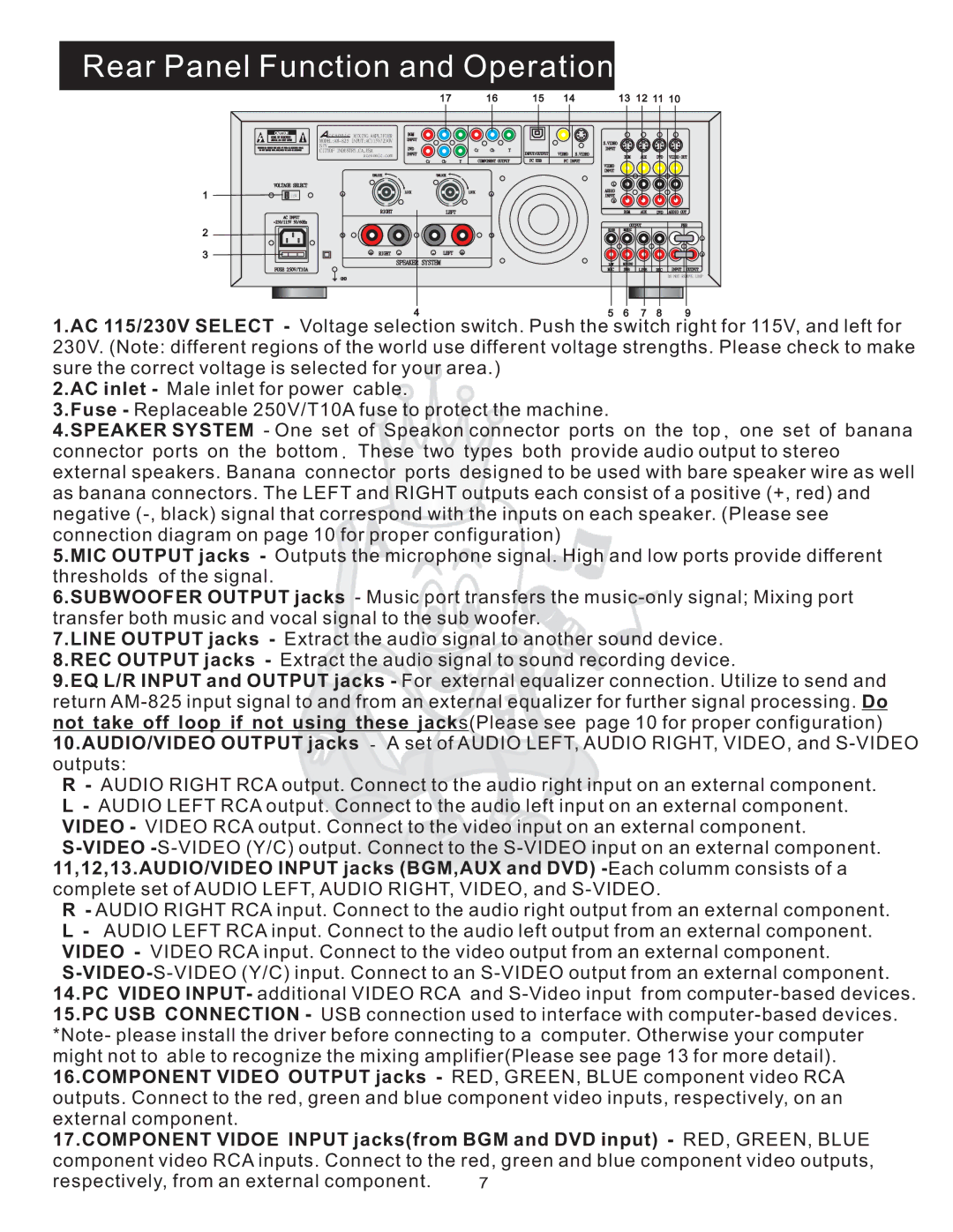
1.AC 115/230V SELECT - Voltage selection switch. Push the switch right for 115V, and left for 230V. (Note: different regions of the world use different voltage strengths. Please check to make sure the correct voltage is selected for your area.)
2.AC inlet - Male inlet for power cable.
3.Fuse - Replaceable 250V/T10A fuse to protect the machine.
4.SPEAKER SYSTEM - One set of Speakon connector ports on the top, one set of banana connector ports on the bottom. These two types both provide audio output to stereo external speakers. Banana connector ports designed to be used with bare speaker wire as well as banana connectors. The LEFT and RIGHT outputs each consist of a positive (+, red) and negative
5.MIC OUTPUT jacks - Outputs the microphone signal. High and low ports provide different thresholds of the signal.
6.SUBWOOFER OUTPUT jacks - Music port transfers the
7.LINE OUTPUT jacks - Extract the audio signal to another sound device. 8.REC OUTPUT jacks - Extract the audio signal to sound recording device.
9.EQ L/R INPUT and OUTPUT jacks - For external equalizer connection. Utilize to send and return
10.AUDIO/VIDEO OUTPUT jacks - A set of AUDIO LEFT, AUDIO RIGHT, VIDEO, and
R- AUDIO RIGHT RCA output. Connect to the audio right input on an external component.
L- AUDIO LEFT RCA output. Connect to the audio left input on an external component. VIDEO - VIDEO RCA output. Connect to the video input on an external component.
S
R- AUDIO RIGHT RCA input. Connect to the audio right output from an external component.
L- AUDIO LEFT RCA input. Connect to the audio left output from an external component. VIDEO - VIDEO RCA input. Connect to the video output from an external component.
S
17.COMPONENT VIDOE INPUT jacks(from BGM and DVD input) - RED, GREEN, BLUE
component video RCA inputs. Connect to the red, green and blue component video outputs,
respectively, from an external component. | 7 |