OUTDOOR LANTERN AND WIRELESS SPEAKER
MODEL AW850
INSTALLATION AND OPERATION MANUAL
INTRODUCTION
AR’s Outdoor Lantern and Wireless Speaker System puts a new twist on your outdoor lighting: sound! The AW850 eliminates the hardest part of adding speakers to your
This manual covers various connection options and detailed operating instructions for making the AR Wireless Speaker System a valued part of your lifestyle. If, after having reviewed the instructions, you have any questions, please call
*Range may vary according to environment.
SETTING UP
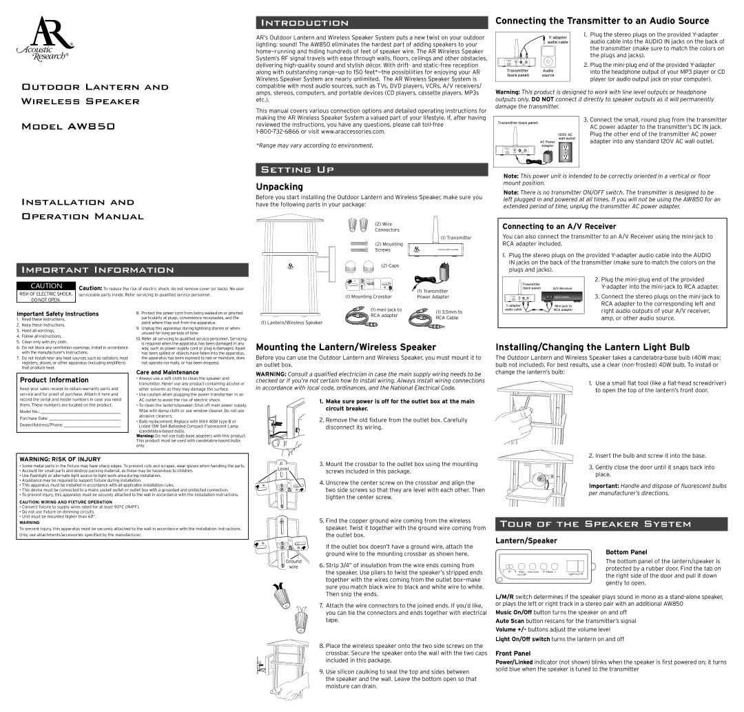
Unpacking
Before you start installing the Outdoor Lantern and Wireless Speaker, make sure you have the following parts in your package:
Connecting the Transmitter to an Audio Source
| 1. | Plug the stereo plugs on the provided | |
|
| audio cable into the AUDIO IN jacks on the back of | |
| audio cable |
| |
|
|
| the transmitter (make sure to match the colors on |
|
|
| the plugs and jacks). |
CHANNEL DC IN | A |
|
|
1 2 3 | 2. | Plug the | |
R AUDIO L |
| ||
IN |
|
| into the headphone output of your MP3 player or CD |
Transmitter | Audio |
| |
|
| ||
(back panel) | source |
| player (or audio output jack on your computer). |
|
|
|
Warning: This product is designed to work with line level outputs or headphone outputs only. DO NOT connect it directly to speaker outputs as it will permanently damage the transmitter.
Transmitter (back panel) | 3. Connect the small, round plug from the transmitter | ||
AC power adapter to the transmitter’s DC IN jack. | |||
|
| ||
| 120V AC | Plug the other end of the transmitter AC power | |
| wall outlet | adapter into any standard 120V AC wall outlet. | |
| AC Power | ||
| Adapter |
| |
CHANNEL | DC IN |
| |
1 2 3 |
|
| |
| R AUDIO L |
| |
| IN |
| |
Note: This power unit is intended to be correctly oriented in a vertical or floor mount position.
Note: There is no transmitter ON/OFF switch. The transmitter is designed to be left plugged in and powered at all times. If you will not be using the AW850 for an extended period of time, unplug the transmitter AC power adapter.
IMPORTANT INFORMATION
CAUTION | Caution: To reduce the risk of electric shock, do not remove cover (or back). No user | |
RISK OF ELECTRIC SHOCK. | ||
serviceable parts inside. Refer servicing to qualified service personnel. | ||
DO NOT OPEN. |
|
(2) Wire
Connectors
(1) Transmitter
(2) Mounting
Screws
(2) Caps |
|
| (1) Transmitter |
(1) Mounting Crossbar | Power Adapter |
Connecting to an A/V Receiver
You can also connect the transmitter to an A/V Receiver using the
1. Plug the stereo plugs on the provided | ||||
IN jacks on the back of the transmitter (make sure to match the colors on the | ||||
plugs and jacks). |
| |||
| Transmitter |
|
| 2. Plug the |
|
|
| ||
| (back panel) |
| A/V Receiver | |
CHANNEL DC IN |
| A | Audio Output | 3. Connect the stereo plugs on the |
1 2 3 | R AUDIO L | |||
| IN |
|
| RCA adapter to the corresponding left and |
|
| |||
Important Safety Instructions
1. | Read these instructions. |
2. | Keep these instructions. |
3. | Heed all warnings. |
4. | Follow all instructions. |
5. | Clean only with dry cloth. |
8. | Protect the power cord from being walked on or pinched |
| particularly at plugs, convenience receptacles, and the |
| point where they exit from the apparatus. |
9. | Unplug this apparatus during lightning storms or when |
| unused for long periods of time. |
10. Refer all servicing to qualified service personnel. Servicing | |
(1) | (1) 3.5mm to | |
RCA adapter | ||
RCA Cable | ||
(1) Lantern/Wireless Speaker | ||
|
audio cable | RCA adapter | right audio outputs of your A/V receiver, |
|
| |
|
| amp, or other audio source. |
6. | Do not block any ventilation openings. Install in accordance |
| with the manufacturer’s instructions. |
7. | Do not install near any heat sources such as radiators, heat |
| registers, stoves, or other apparatus (including amplifiers) |
| that produce heat. |
Product Information
Keep your sales receipt to obtain warranty parts and service and for proof of purchase. Attach it here and
is required when the apparatus has been damaged in any |
way, such as |
has been spilled or objects have fallen into the apparatus, |
the apparatus has been exposed to rain or moisture, does |
not operate normally, or has been dropped. |
Care and Maintenance
• Always use a soft cloth to clean the speaker and |
transmitter. Never use any product containing alcohol or |
other solvents as they may damage the surface. |
• Use caution when plugging the power transformer in an |
Mounting the Lantern/Wireless Speaker
Before you can use the Outdoor Lantern and Wireless Speaker, you must mount it to an outlet box.
WARNING: Consult a qualified electrician in case the main supply wiring needs to be checked or if you’re not certain how to install wiring. Always install wiring connections
in accordance with local code, ordinances, and the National Electrical Code.
Installing/Changing the Lantern Light Bulb
The Outdoor Lantern and Wireless Speaker takes a
1.Use a small flat tool (like a
record the serial and model numbers in case you need them. These numbers are located on the product.
Model No.:_______________________________________
Purchase Date:___________________________________
Dealer/Address/Phone:____________________________
AC outlet to avoid the risk of electric shock. |
• To clean the lantern/speaker: Shut off main power supply. |
Wipe with damp cloth or use window cleaner. Do not use |
abrasive cleaners. |
• Bulb replacement: Replace with MAX 40W type B or |
Listed 13W |
Warning: Do not use
1. | Make sure power is off for the outlet box at the main |
| circuit breaker. |
2. | Remove the old fixture from the outlet box. Carefully |
| disconnect its wiring. |
WARNING: RISK OF INJURY
•Some metal parts in the fixture may have sharp edges. To prevent cuts and scrapes, wear gloves when handling the parts.
•Account for small parts and destroy packing material, as these may be hazardous to children.
•Use flashlight or alternate light source to light work area during installation.
•Assistance may be required to support fixture during installation.
•This apparatus must be installed in accordance with all applicable installation rules.
•This device must be connected to a mains socket outlet or outlet box with a grounded and protected connection.
•To prevent injury, this apparatus must be securely attached to the wall in accordance with the installation instructions.
CAUTION: WIRING AND FIXTURE OPERATION
•Connect fixture to supply wires rated for at least 90°C (194°F).
•Do not use fixture on dimming circuits.
•Unit must be mounted higher than 60”.
WARNING
To prevent injury, this apparatus must be securely attached to the wall in accordance with the installation instructions. Only use attachments/accessories specified by the manufacturer.
Level
Ground
wire
3. | Mount the crossbar to the outlet box using the mounting |
| screws included in this package. |
4. Unscrew the center screw on the crossbar and align the | |
| two side screws so that they are level with each other. Then |
| tighten the center screw. |
5. | Find the copper ground wire coming from the wireless |
| speaker. Twist it together with the ground wire coming from |
| the outlet box. |
| If the outlet box doesn’t have a ground wire, attach the |
| ground wire to the mounting crossbar as shown here. |
6. Strip 3/4” of insulation from the wire ends coming from | |
| the speaker. Use pliers to twist the speaker’s stripped ends |
| together with the wires coming from the outlet |
| sure you match black wire to black and white wire to white. |
| Then snip the ends. |
7. | Attach the wire connectors to the joined ends. If you’d like, |
| you can tie the connectors and ends together with electrical |
| tape. |
8. Place the wireless speaker onto the two side screws on the | |
| crossbar. Secure the speaker onto the wall with the two caps |
| included in this package. |
9. | Use silicon caulking to seal the top and sides between |
| the speaker and the wall. Leave the bottom open so that |
| moisture can drain. |
2.Insert the bulb and screw it into the base.
3.Gently close the door until it snaps back into place.
Important: Handle and dispose of fluorescent bulbs per manufacturer’s directions.
TOUR OF THE SPEAKER SYSTEM
Lantern/Speaker
Bottom Panel
The bottom panel of the lantern/speaker is protected by a rubber door. Find the tab on the right side of the door and pull it down gently to open.
L/M/R switch determines if the speaker plays sound in mono as a
Music On/Off button turns the speaker on and off Auto Scan button rescans for the transmitter’s signal Volume +/– buttons adjust the volume level
Light On/Off switch turns the lantern on and off
Front Panel
Power/Linked indicator (not shown) blinks when the speaker is first powered on; it turns solid blue when the speaker is tuned to the transmitter