6 / 0 8 • 1 0 4 3 4 7 A E
BNC-26N Straight Connector for 0.6/2.8 Cables
Specifications
ELECTRICAL |
|
Characteristic Impedance: | 75 Ohm |
Voltage Rating: | 1000 Volts RMS |
Insertion Loss: | < 0.6 dB 1 MHz to 1 GHz (measured with 1 meter of 728 cable) |
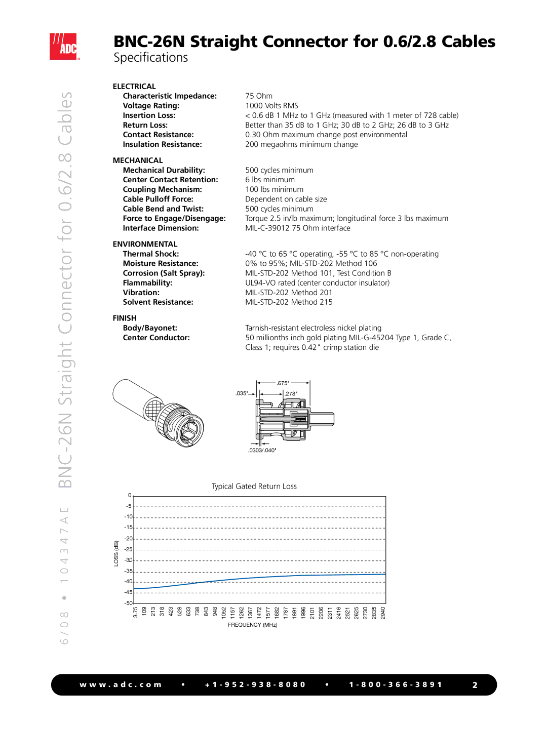
Return Loss: | Better than 35 dB to 1 GHz; 30 dB to 2 GHz; 26 dB to 3 GHz |
Contact Resistance: | 0.30 Ohm maximum change post environmental |
Insulation Resistance: | 200 megaohms minimum change |
MECHANICAL |
|
Mechanical Durability: | 500 cycles minimum |
Center Contact Retention: | 6 lbs minimum |
Coupling Mechanism: | 100 lbs minimum |
Cable Pulloff Force: | Dependent on cable size |
Cable Bend and Twist: | 500 cycles minimum |
Force to Engage/Disengage: | Torque 2.5 in/lb maximum; longitudinal force 3 lbs maximum |
Interface Dimension: | |
ENVIRONMENTAL |
|
Thermal Shock: | |
Moisture Resistance: | 0% to 95%; |
Corrosion (Salt Spray): | |
Flammability: | |
Vibration: | |
Solvent Resistance: |
FINISH
Body/Bayonet:Tarnish-resistant electroless nickel plating
Center Conductor:50 millionths inch gold plating
.675" | |
.035" | .278" |
.0303/.040" |
|
Typical Gated Return Loss
| 0 | |
| ||
| ||
| ||
(dB) | ||
LOSS | ||
| - | |
|
3.75 | 109 | 213 | 318 | 423 | 528 | 633 | 738 | 843 | 948 | 1052 | 1157 | 1262 | 1367 | 1472 | 1577 | 1682 | 1787 | 1891 | 1996 | 2101 | 2206 | 2311 | 2416 | 2521 | 2625 | 2730 | 2835 | 2940 |
|
|
|
|
|
|
|
|
|
|
| FREQUENCY (MHz) |
|
|
|
|
|
|
|
|
|
|
|
| |||||
w w w . a d c . c o m | • | + 1 - 9 5 2 - 9 3 8 - 8 0 8 0 | • | 1 - 8 0 0 - 3 6 6 - 3 8 9 1 | 2 |
