8 / 0 7 • 1 0 5 1 8 8 A E ClearGain Dual Inline TMAs
ClearGain® Dual Inline TMAs
Americas
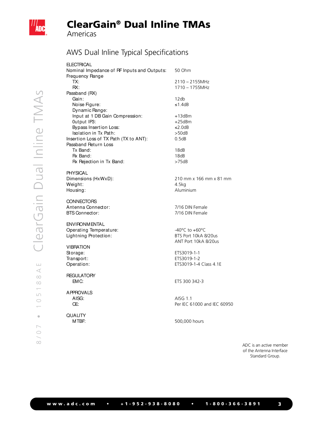
AWS Dual Inline Typical Specifications
ELECTRICAL |
|
Nominal Impedance of RF Inputs and Outputs: | 50 Ohm |
Frequency Range |
|
TX: | 2110 – 2155MHz |
RX: | 1710 – 1755MHz |
Passband (RX) |
|
Gain: | 12db |
Noise Figure: | ≤1.4dB |
Dynamic Range: |
|
Input at 1 DB Gain Compression: | +13dBm |
0utput IP3: | +25dBm |
Bypass Insertion Loss: | ≤2.0dB |
Isolation in Tx Path: | >50dB |
Insertion Loss of TX Path (TX to ANT): | 0.5dB |
Passband Return Loss |
|
Tx Band: | 18dB |
Rx Band: | 18dB |
Rx Rejection in Tx Band: | >75dB |
PHYSICAL |
|
Dimensions (HxWxD): | 210 mm x 166 mm x 81 mm |
Weight: | 4.5kg |
Housing: | Aluminium |
CONNECTORS |
|
Antenna Connector: | 7/16 DIN Female |
BTS Connector: | 7/16 DIN Female |
ENVIRONMENTAL |
|
Operating Temperature: | |
Lightning Protection: | BTS Port 10kA 8/20us |
| ANT Port 10kA 8/20us |
VIBRATION |
|
Storage: | |
Transport: | |
Operation: | |
REGULATORY |
|
EMC: | ETS 300 |
APPROVALS |
|
AISG: | AISG 1.1 |
CE: | Per IEC 61000 and IEC 60950 |
QUALITY |
|
MTBF: | 500,000 hours |
ADC is an active member of the Antenna Interface Standard Group.
w w w . a d c . c o m | • | + 1 - 9 5 2 - 9 3 8 - 8 0 8 0 | • | 1 - 8 0 0 - 3 6 6 - 3 8 9 1 |
