The trunk processing options are provisioned only by switch SW7. Electronic provisioning is not available.
Table C provides a guide to ensure proper provisioning of the desired channel unit mode.
Table C. Manual Configuration Guide
| FXS | FXS | TANDEM | TANDEM |
|
|
Options | Loop | Gnd | Loop | Gnd | PLAR | DPO |
| Start | Start | Start | Start |
|
|
RTG | X | X | On/Off | On/Off | On | X |
|
|
|
|
|
| |
|
|
|
|
|
|
|
DTG | X | X | On/Off | On/Off | X | X |
|
|
|
|
|
| |
|
|
|
|
|
|
|
TWS | X | X | On/Off | On/Off | X | X |
|
|
|
|
|
| |
|
|
|
|
|
|
|
TRB | X | X | On/Off | On/Off | X | X |
|
|
|
|
|
| |
|
|
|
|
|
|
|
PD3 | X | X | X | X | On/Off | X |
|
|
|
|
|
| |
|
|
|
|
|
|
|
GS | Off | On | Off | On | X | X |
|
|
|
|
|
| |
|
|
|
|
|
|
|
DPC | On/Off | On/Off | X | X | X | X |
|
|
|
|
|
| |
|
|
|
|
|
|
|
SD | On/Off | On/Off | On/Off | On/Off | On/Off | On/Off |
|
|
|
|
|
| |
|
|
|
|
|
|
|
TNDM | Off | Off | On | On | Off | Off |
|
|
|
|
|
| |
|
|
|
|
|
|
|
PLAR | Off | Off | Off | Off | On | Off |
|
|
|
|
|
| |
|
|
|
|
|
|
|
FXS | On | On | Off | Off | Off | Off |
|
|
|
|
|
| |
|
|
|
|
|
|
|
DPO | Off | Off | Off | Off | Off | On |
|
|
|
|
|
|
Note: X = Switch position is ignored.
Electronic Provisioning
ADTRAN EASYMENU is used to electronically provision the unit. Connect a VT 100 terminal or a computer running a terminal emulation program to the faceplate ADMIN port or REMOTE port using a standard
A null modem cable is required to connect the REMOTE port directly to a terminal.
Table D. Electronic Provisioning Settings
| ADMIN Port | REMOTE Port |
Settings | 9600 baud | SW2 baud |
| No Parity | No Parity |
| 8 bits | 8 bits |
| 1 stop bit | 1 stop bit |
Once connected, enter the password. The factory default password is PASSWORD in all capital letters. The password may be changed by selecting:
Common Module Menus | (2) |
BCU | (1) |
Configuration | (1) |
Read/Write Password | (9) |
Before provisioning the unit electronically, access the channel unit by selecting:
Channel Unit Menus | (3) |
Desired slot | |
Provisioning | (2) |
Select current operational mode | |
Select desired provisioning option |
For additional information on EASYMENU operation or the ADTRAN Site Manager, refer to the EASYMENU User Manual, document number
Initial Turn-up
Refer to the desired operational mode in Table C for the correct provisioning options.
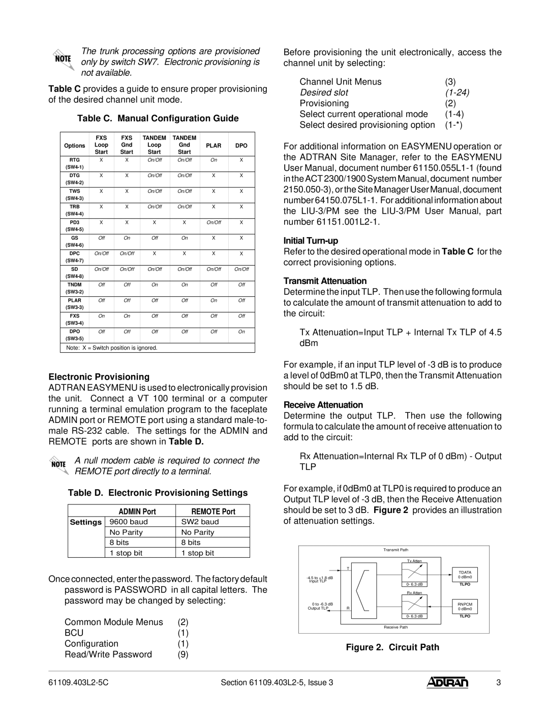
Transmit Attenuation
Determine the input TLP. Then use the following formula to calculate the amount of transmit attenuation to add to the circuit:
Tx Attenuation=Input TLP + Internal Tx TLP of 4.5 dBm
For example, if an input TLP level of
Receive Attenuation
Determine the output TLP. Then use the following formula to calculate the amount of receive attenuation to add to the circuit:
Rx Attenuation=Internal Rx TLP of 0 dBm) - Output
TLP
For example, if 0dBm0 at TLP0 is required to produce an Output TLP level of
| Transmit Path |
|
| Tx Atten |
|
| T | TDATA |
|
| |
| 0 dBm0 | |
Input TLP | 0- 6.3 dB | TLPO |
| ||
| Rx Atten |
|
0 to |
| RNPCM |
Output TLP | R | 0 dBm0 |
| 0- 6.3 dB | TLPO |
| Receive Path |
|
Figure 2. Circuit Path
Section |
| 3 |