3. CONNECTIONS
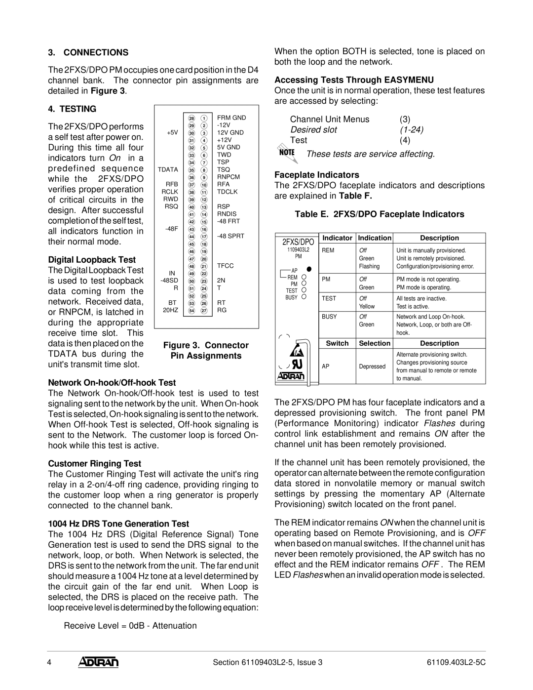
The 2FXS/DPO PM occupies one card position in the D4 channel bank. The connector pin assignments are detailed in Figure 3.
When the option BOTH is selected, tone is placed on both the loop and the network.
Accessing Tests Through EASYMENU
Once the unit is in normal operation, these test features are accessed by selecting:
4. TESTING
The 2FXS/DPO performs a self test after power on. During this time all four indicators turn On in a predefined sequence while the 2FXS/DPO verifies proper operation of critical circuits in the design. After successful completion of the self test, all indicators function in their normal mode.
Digital Loopback Test
The Digital Loopback Test is used to test loopback data coming from the network. Received data, or RNPCM, is latched in during the appropriate receive time slot. This data is then placed on the TDATA bus during the unit's transmit time slot.
| 28 | 1 | FRM GND |
| 29 | 2 | |
+5V | 30 | 3 | 12V GND |
| 31 | 4 | +12V |
| 32 | 5 | 5V GND |
| 33 | 6 | TWD |
| 34 | 7 | TSP |
TDATA | 35 | 8 | TSQ |
| 36 | 9 | RNPCM |
RFB | 37 | 10 | RFA |
RCLK | 38 | 11 | TDCLK |
RWD | 39 | 12 |
|
RSQ | 40 | 13 | RSP |
| 41 | 14 | RNDIS |
| 42 | 15 | |
43 | 16 |
| |
| 44 | 17 | |
| 45 | 18 |
|
| 46 | 19 |
|
| 47 | 20 |
|
| 48 | 21 | TFCC |
IN | 49 | 22 |
|
50 | 23 | 2N | |
R | 51 | 24 | T |
| 52 | 25 |
|
BT | 53 | 26 | RT |
20HZ | 54 | 27 | RG |
Figure 3. Connector
Pin Assignments
Channel Unit Menus | (3) |
Desired slot | |
Test | (4) |
These tests are service affecting.
Faceplate Indicators
The 2FXS/DPO faceplate indicators and descriptions are explained in Table F.
Table E. 2FXS/DPO Faceplate Indicators
|
|
|
|
| Indicator | Indication | Description |
| 2FXS/DPO |
| |||||
|
|
|
| ||||
|
| 1109403L2 |
| REM | Off | Unit is manually provisioned. | |
|
|
| PM |
|
| Green | Unit is remotely provisioned. |
|
|
|
|
|
| ||
|
|
| AP |
|
| Flashing | Configuration/provisioning error. |
|
| REM |
| PM | Off | PM mode is not operating. | |
|
|
| |||||
|
|
| PM |
| |||
|
|
|
|
| Green | PM mode is operating. | |
| TEST |
|
| ||||
|
|
|
|
| |||
| BUSY |
| TEST | Off | All tests are inactive. | ||
|
|
|
|
|
| Yellow | Test is active. |
|
|
|
|
|
|
|
|
|
|
|
|
| BUSY | Off | Network and Loop |
|
|
|
|
|
| Green | Network, Loop, or both are Off- |
|
|
|
|
|
|
| hook. |
|
|
|
|
|
|
|
|
|
|
|
|
| Switch | Selection | Description |
|
|
|
|
|
|
|
|
|
|
|
|
|
|
| Alternate provisioning switch. |
|
|
|
|
| AP | Depressed | Changes provisioning source |
|
|
|
|
| from manual to remote or remote | ||
|
|
|
|
|
|
| |
|
|
|
|
|
|
| to manual. |
Network On-hook/Off-hook Test
The Network
Customer Ringing Test
The Customer Ringing Test will activate the unit's ring relay in a
1004 Hz DRS Tone Generation Test
The 1004 Hz DRS (Digital Reference Signal) Tone Generation test is used to send the DRS signal to the network, loop, or both. When Network is selected, the DRS is sent to the network from the unit. The far end unit should measure a 1004 Hz tone at a level determined by the circuit gain of the far end unit. When Loop is selected, the DRS is placed on the receive path. The loop receive level is determined by the following equation:
Receive Level = 0dB - Attenuation
The 2FXS/DPO PM has four faceplate indicators and a depressed provisioning switch. The front panel PM (Performance Monitoring) indicator Flashes during control link establishment and remains ON after the channel unit has been remotely provisioned.
If the channel unit has been remotely provisioned, the operator can alternate between the remote configuration data stored in nonvolatile memory or manual switch settings by pressing the momentary AP (Alternate Provisioning) switch located on the front panel.
The REM indicator remains ON when the channel unit is operating based on Remote Provisioning, and is OFF when based on manual switches. If the channel unit has never been remotely provisioned, the AP switch has no effect and the REM indicator remains OFF . The REM LED Flashes when an invalid operation mode is selected.
4 |
| Section |