JOBAID
TECHNICAL SUPPORT 800.726.8663
9904
TRI-C DP/ BR1/10
CLEI:D4CIA9T2
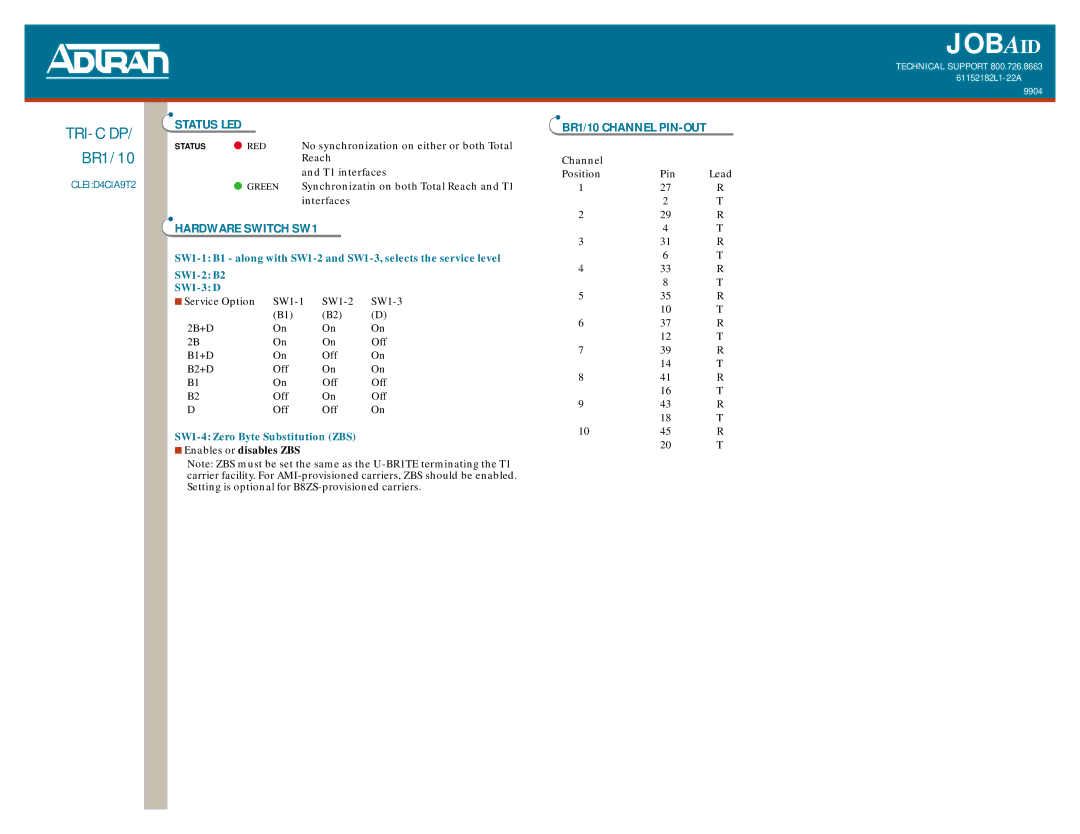
STATUS LED
STATUS | ● RED | No synchronization on either or both Total |
|
| Reach |
|
| and T1 interfaces |
| ● GREEN | Synchronizatin on both Total Reach and T1 |
|
| interfaces |
HARDWARE SWITCH SW1
|
|
| |
|
|
| |
■ Service Option | |||
| (B1) | (B2) | (D) |
2B+D | On | On | On |
2B | On | On | Off |
B1+D | On | Off | On |
B2+D | Off | On | On |
B1 | On | Off | Off |
B2 | Off | On | Off |
D | Off | Off | On |
■Enables or disables ZBS
Note: ZBS must be set the same as the
BR1/10 CHANNEL PIN-OUT
Channel |
|
|
Position | Pin | Lead |
1 | 27 | R |
| 2 | T |
2 | 29 | R |
| 4 | T |
3 | 31 | R |
| 6 | T |
4 | 33 | R |
| 8 | T |
5 | 35 | R |
| 10 | T |
6 | 37 | R |
| 12 | T |
7 | 39 | R |
| 14 | T |
8 | 41 | R |
| 16 | T |
9 | 43 | R |
| 18 | T |
10 | 45 | R |
| 20 | T |
