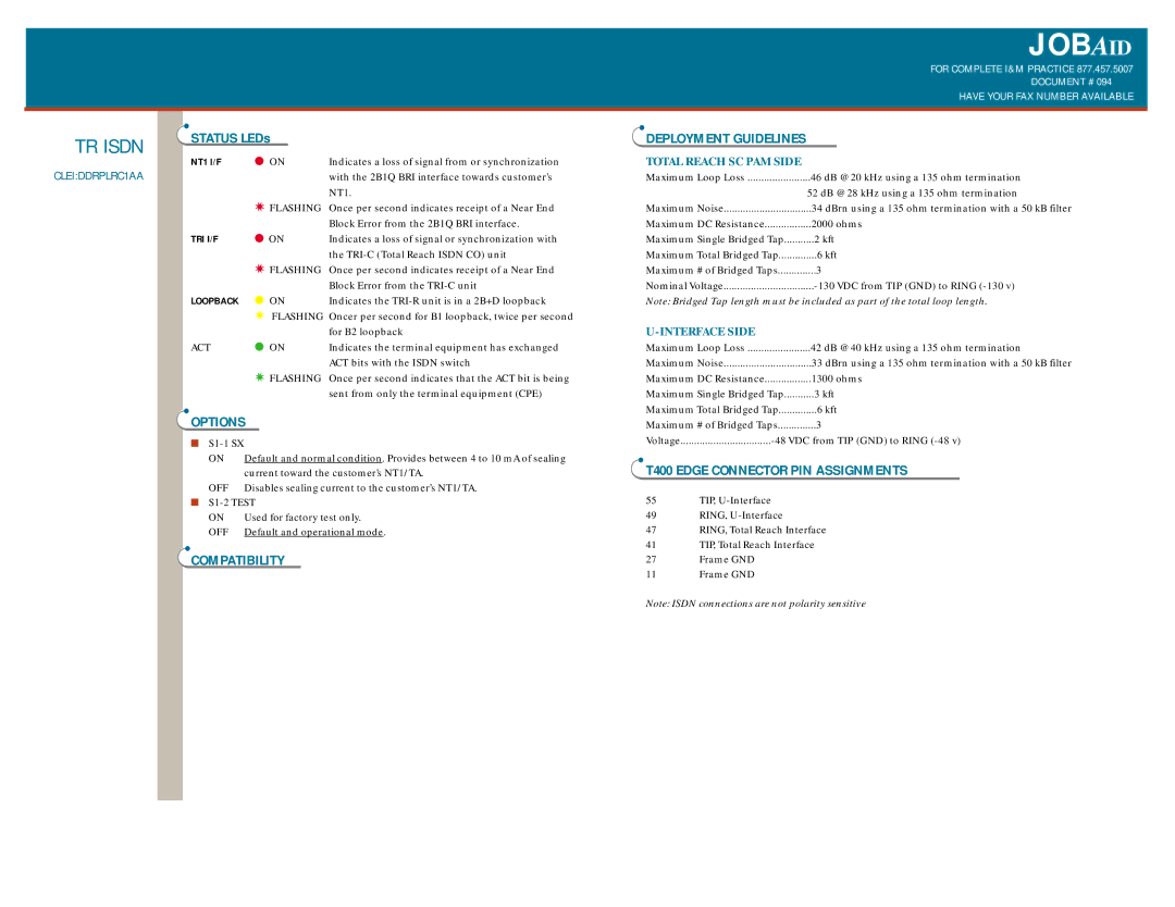
JOBAID
FOR COMPLETE I&M PRACTICE 877.457.5007
DOCUMENT # 094
|
|
|
|
|
| HAVE YOUR FAX NUMBER AVAILABLE |
|
|
|
|
|
|
|
TR ISDN | STATUS LEDs |
| DEPLOYMENT GUIDELINES |
| ||
|
|
| ||||
CLEI:DDRPLRC1AA | NT1 I/F | ● ON | Indicates a loss of signal from or synchronization | TOTAL REACH SC PAM SIDE |
| |
|
| with the 2B1Q BRI interface towards customer’s | Maximum Loop Loss | 46 dB @ 20 kHz using a 135 ohm termination | ||
|
|
| NT1. |
|
| 52 dB @ 28 kHz using a 135 ohm termination |
|
| ✷ FLASHING | Once per second indicates receipt of a Near End | Maximum Noise | 34 dBrn using a 135 ohm termination with a 50 kB filter | |
|
|
| Block Error from the 2B1Q BRI interface. | Maximum DC Resistance | 2000 ohms | |
| TRI I/F | ● ON | Indicates a loss of signal or synchronization with | Maximum Single Bridged Tap | 2 kft | |
|
|
| the | Maximum Total Bridged Tap | 6 kft | |
|
| ✷ FLASHING | Once per second indicates receipt of a Near End | Maximum # of Bridged Taps | 3 | |
|
|
| Block Error from the | Nominal Voltage | ||
| LOOPBACK | ● ON | Indicates the | Note: Bridged Tap length must be included as part of the total loop length. | ||
|
| ✷ FLASHING Oncer per second for B1 loopback, twice per second |
|
|
| |
|
|
| for B2 loopback |
|
|
|
| ACT | ● ON | Indicates the terminal equipment has exchanged | Maximum Loop Loss | 42 dB @ 40 kHz using a 135 ohm termination | |
|
|
| ACT bits with the ISDN switch | Maximum Noise | 33 dBrn using a 135 ohm termination with a 50 kB filter | |
|
| ✷ FLASHING | Once per second indicates that the ACT bit is being | Maximum DC Resistance | 1300 ohms | |
|
|
| sent from only the terminal equipment (CPE) | Maximum Single Bridged Tap | 3 kft | |
| OPTIONS |
|
| Maximum Total Bridged Tap | 6 kft | |
|
|
| Maximum # of Bridged Taps | 3 | ||
|
|
|
| Voltage | ||
Default and normal condition. Provides between 4 to 10 mA of sealing current toward the customer’s NT1/TA.
OFF Disables sealing current to the customer’s NT1/TA.
■
ON | Used for factory test only. |
OFF | Default and operational mode. |
COMPATIBILITY
T400 EDGE CONNECTOR PIN ASSIGNMENTS
55 | TIP, |
49 | RING, |
47 | RING, Total Reach Interface |
41 | TIP, Total Reach Interface |
27 | Frame GND |
11 | Frame GND |
Note: ISDN connections are not polarity sensitive
