BR1/10 2X MINI ISDN CHANNEL BANK

PRICING AND AVAILABILITY 800.827.0807 TECH SUPPORT 800.726.8663 RETURN FOR REPAIR 256.963.8722 www.adtran.com 61150081L2-22A

BCU DIP Test Switch

Channel Selection

BCU LEDs

Indicator

Color

Description

AY

Amber

ON indicates a Yellow Alarm is being received from the T1 carrier facility

AR

Red

ON indicates the BR1/10 side is in a Red Alarm condition

TP

Amber

ON indicates Trunk Processing is active on all U-BRITEs (10)

RCV

Red

ON indicates a loss of framing of T1 signal from the T1 carrier facility

ESF

Green

ON indicates the T1 Extended SuperFrame format is selected


11

LIU


1


50079L2

10

2


9


3


8


4

T


7

6

5

E


S


CRTX


T


LPBX

LPTX


AD


NT1


R6


AD


AD


R5


R1


ADR4

ADR3

ADR2


IN


M


O


N


OUT


DB-9 Connector


Bantam Jacks

LB ON

1

OFF

AY

REMOTE


AR

2

LOC

DS0


TP

3

DS1

RCV

B2


4

B1

ESF


SF

TEST

B8ZS

AMI


10DSL

BDSL


EXT

LOC


LOOP

CAU


DS1-LOC

RMT


LP-SYNC

CRC


CR-SYNC

CRC


DSO-LB

ACT

BCU

1150080L1

Loopback Address


ON


8

9

10


7


6


5


4


3


1

2


Recessed Test Push Button

SF

Green

ON indicates the T1 SuperFrame format is selected

B8ZS

Green

ON indicates T1 B8ZS line coding is selected

AMI

Green

ON indicates T1 AMI line coding is selected

10DSL

Green

ON indicates D Channel 4:1 TDM mode is selected to transport 10 BRIs

8DSL

Green

ON indicates TR-397 3-DS0 framing across the T1 facility to transport 8 BRIs

EXT

Green

ON indicates External timing input is selected (BITS)

LOC

Green

ON indicates BR1/10 side is using a locally generated clock source to time the


T1 network

LOOP

Green

ON indicates BR1/10 clock is recovered clock from the T1 network

CAU

Green

ON indicates clock is recovered from the DSL position #1 to time the T1 network

DS1-LOC

Green

ON indicates the BR1/10 side is in a Local DS1 Loopback

RMT

Green

ON indicates the unit has initiated remote DS1 loopback when set in ESF mode


FLASHING indicates it responded to remotely commanded loopback, or has


provided a loopback path for the T1 data-stream in SF mode

LP-SYNC*

Red

ON indicates the U-interface is out of sync for the selected channel unit

LP-CRC*

Red

In normal operation flashes upon receiving NEBEs from the loop. In Local PM


mode flashes 6-19 CRCs and is solid when >20 CRC errors are detected from the


loop

LOOPBACK TEST (ADR6, NT1)

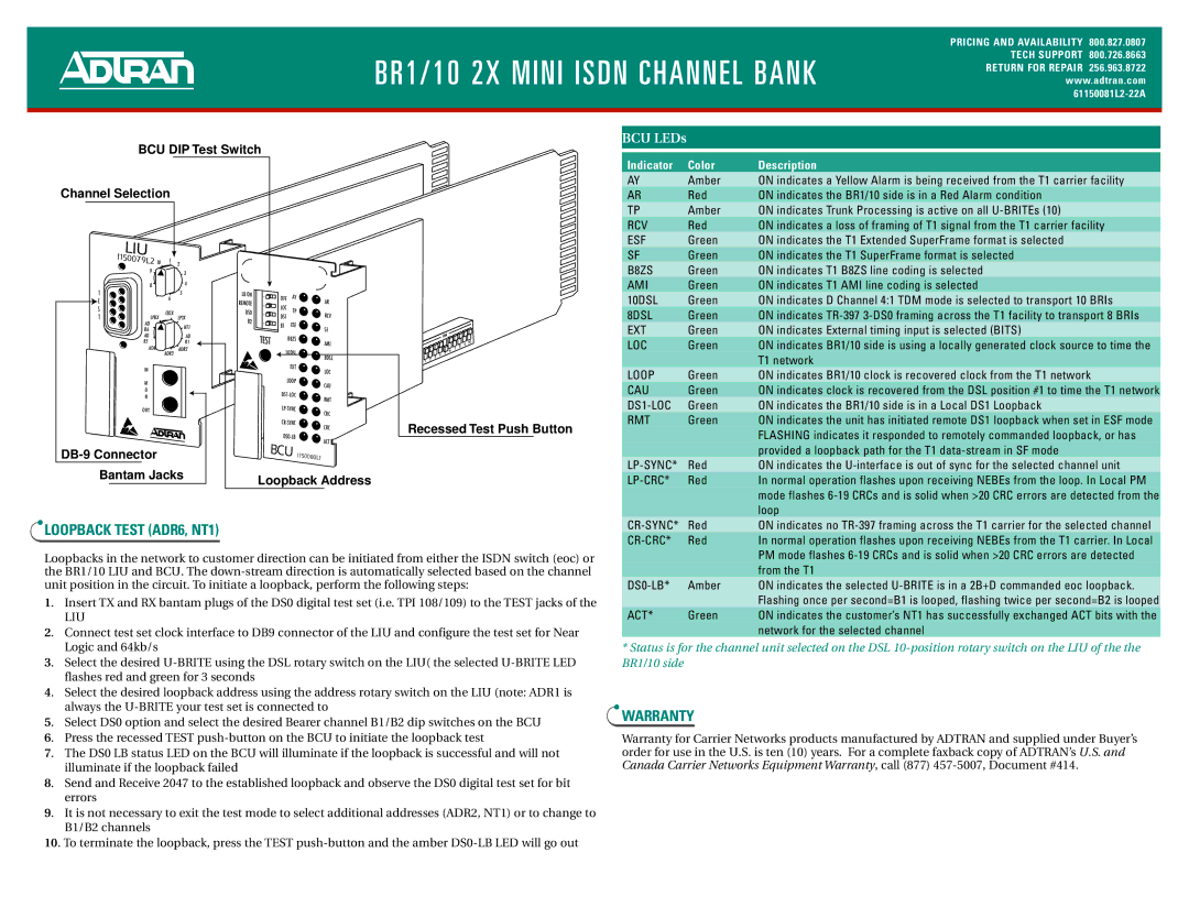
Loopbacks in the network to customer direction can be initiated from either the ISDN switch (eoc) or the BR1/10 LIU and BCU. The down-stream direction is automatically selected based on the channel unit position in the circuit. To initiate a loopback, perform the following steps:

1. Insert TX and RX bantam plugs of the DS0 digital test set (i.e. TPI 108/109) to the TEST jacks of the

LIU

2. Connect test set clock interface to DB9 connector of the LIU and configure the test set for Near Logic and 64kb/s

3. Select the desired U-BRITE using the DSL rotary switch on the LIU( the selected U-BRITE LED flashes red and green for 3 seconds

4. Select the desired loopback address using the address rotary switch on the LIU (note: ADR1 is always the U-BRITE your test set is connected to

5. Select DS0 option and select the desired Bearer channel B1/B2 dip switches on the BCU

6. Press the recessed TEST push-button on the BCU to initiate the loopback test

7. The DS0 LB status LED on the BCU will illuminate if the loopback is successful and will not illuminate if the loopback failed

8. Send and Receive 2047 to the established loopback and observe the DS0 digital test set for bit errors

9. It is not necessary to exit the test mode to select additional addresses (ADR2, NT1) or to change to B1/B2 channels

10. To terminate the loopback, press the TEST push-button and the amber DS0-LB LED will go out

CR-SYNC*

Red

ON indicates no TR-397 framing across the T1 carrier for the selected channel

CR-CRC*

Red

In normal operation flashes upon receiving NEBEs from the T1 carrier. In Local


PM mode flashes 6-19 CRCs and is solid when >20 CRC errors are detected


from the T1

DS0-LB*

Amber

ON indicates the selected U-BRITE is in a 2B+D commanded eoc loopback.


Flashing once per second=B1 is looped, flashing twice per second=B2 is looped

ACT*

Green

ON indicates the customer’s NT1 has successfully exchanged ACT bits with the


network for the selected channel

*Status is for the channel unit selected on the DSL 10-position rotary switch on the LIU of the the BR1/10 side

WARRANTY

Warranty for Carrier Networks products manufactured by ADTRAN and supplied under Buyer’s order for use in the U.S. is ten (10) years. For a complete faxback copy of ADTRAN’s U.S. and Canada Carrier Networks Equipment Warranty, call (877) 457-5007, Document #414.

Page 2
Image 2
ADTRAN BR10 manual Loopback Test ADR6, NT1, Warranty

BR10 specifications

ADTRAN BR10 is a versatile broadband router designed to meet the requirements of modern networking environments. It serves as an essential device for service providers and businesses, enabling high-speed data transmission and efficient network management. The BR10 stands out due to its robust features and support for advanced technologies, making it ideal for a wide range of applications.

One of the primary features of the ADTRAN BR10 is its multi-gigabit Ethernet capacity, which supports high-speed connections up to 10 Gbps. This capability is crucial for organizations that require significant bandwidth to accommodate an increasing number of connected devices and the demand for data-rich applications. The device is equipped with various Ethernet ports and supports both copper and fiber connections, offering flexibility for different networking setups.

Another notable characteristic of the BR10 is its support for various access protocols, including passive optical networking (PON) and Ethernet. This adaptability allows service providers to leverage existing infrastructure while planning for future upgrades, making it a cost-effective solution for expanding network capabilities.

In terms of security, the BR10 incorporates advanced security protocols such as firewall protection, virtual private network (VPN) support, and intrusion prevention systems. These features ensure that data transfers remain secure, protecting sensitive information from potential threats. Additionally, the device offers network management tools that enable easy monitoring and troubleshooting, contributing to reduced downtime and enhanced operational efficiency.

The ADTRAN BR10 also supports Quality of Service (QoS) features, ensuring that critical applications receive the bandwidth they require. This functionality is particularly important for businesses that rely on real-time communications and streaming services, as it helps maintain performance even under heavy network load.

With its compact design and rack-mountable options, the BR10 can fit seamlessly into various environments, whether in data centers or local networking closets. Moreover, the device is user-friendly, providing an intuitive interface for configuration and management that simplifies the setup process for IT teams.

In conclusion, the ADTRAN BR10 is a powerful broadband router that combines high-speed connectivity, versatile protocol support, advanced security features, and effective network management capabilities. These characteristics make it a reliable choice for businesses and service providers looking to enhance their networking infrastructure.