3.LOOPBACK ACTIVATION AND DEACTIVATION
This section describes loopback activation and deactivation methods for the ADTRAN Fractional T1 system. Loopback activation and deactivation is controlled with the
A
Craft interfaces, located on the front panels of the FNID and FT1Ê DP, allow access to the FT1 device through an
Latching loopbacks for the FT1 system are activated by transmitting the following latching loopback sequence in the primary DS0 of the FT1 system:
A.Minimum of 35 transition in progress (TIP) bytes (N0111010).
B.Minimum of 35 loopback select code (LSC) bytes as defined in Table
C.Minimum of 100 loopback enable (LBE) bytes (N1010110).
D.Minimum of 35 all 1s bytes (S1111111), plus a minimum of 100 LBE bytes.
E. Minimum of 32 far end voice (FEV) bytes (N1011010).
A
Latching loopbacks for the FT1 system are deactivated by transmitting the following latching loopback sequence in the primary DS0 of the FT1 system:
Minimum of 25 TIP bytes (N0111010)
FT1 DP, FT1 Repeater, and FNID network loopbacks can be activated by the DDS latching loopback sequence. The latching loopback sequence is detected in the primary DS0 of the FT1 system. When the loopback is activated on the device, the whole FT1 bandwidth is looped. The FT1 DP, FT1 Repeater, and FNID each respond to a different loopback select code allowing for sectionalization of the network during testing. Table
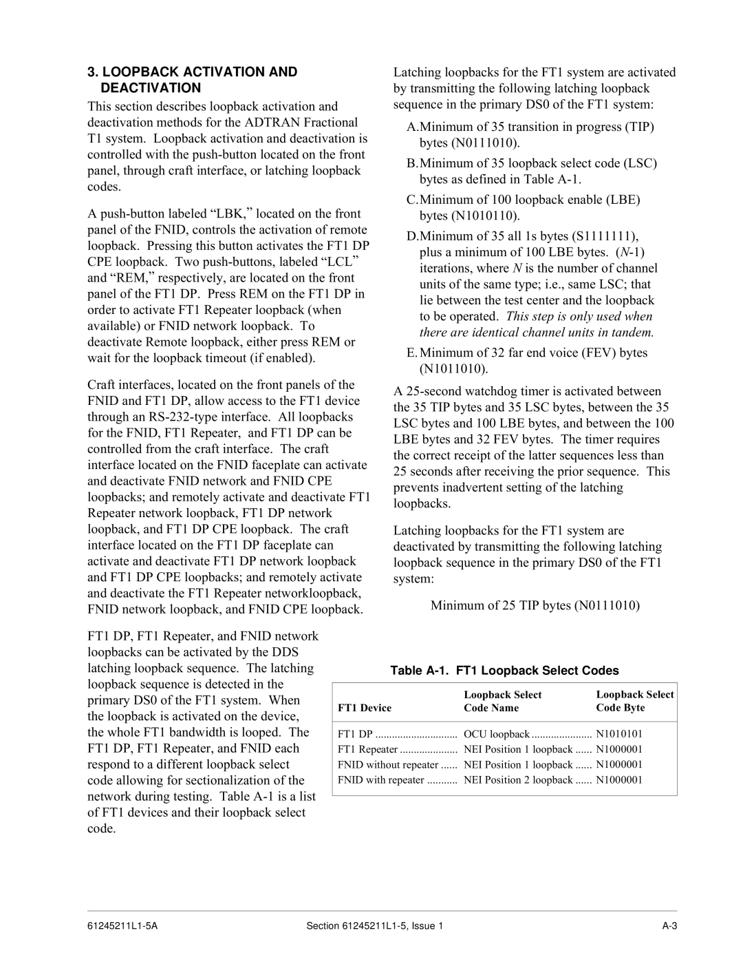
Table A-1. FT1 Loopback Select Codes
| Loopback Select | Loopback Select |
FT1 Device | Code Name | Code Byte |
|
|
|
FT1 DP | OCU loopback | N1010101 |
FT1 Repeater | NEI Position 1 loopback | N1000001 |
FNID without repeater | NEI Position 1 loopback | N1000001 |
FNID with repeater | NEI Position 2 loopback | N1000001 |
|
|
|
Section |