JOBAID
TOTAL ACCESS | ® | OPTI - T200 | |
| |||
|
|
| 0309 |
|
|
|
|
OPTI-T200
CLEI: SOI4JN6D_ _
OPTI-T200
1310 nm
1184400L1
TX
DS3
RX ![]()
STATUS
OPTICS
DS3
E |
N |
E |
T |
TX |
RX
C
R
A
F
T
LED STATUS
STATUS ● | Off | No power to unit |
● | Green | Power up and initialization OK |
● | Yellow | Unit is in |
✷ | Flashing Yellow | Unit is in |
● | Red | Unit has an equipment failure |
OPTICS ● | Green | Normal Operation |
● | Yellow | Soft failure (e.g. RDI) |
✷ | Flashing Yellow | Unit in Test (e.g. Loopback) |
● Red | LOS, LOL, or other hard alarms on optical | |
|
| interface |
✷ Flashing Red | Unit in Test (e.g. Loopback) with an alarm present | |
|
| on the Optical Interface |
DS3 ● Off | DS3 disabled | |
● Green | DS3 normal operation | |
● Yellow | Soft failure (e.g. RDI) | |
✷ Flashing Yellow | Unit in Test (e.g. Loopback) | |
● Red | LOS, LOL, or other hard alarms on DS3 interface | |
✷ Flashing Red | Unit in Test (e.g. Loopback) with an alarm present | |
|
| on the DS3 Interface |
CRAFT INTERFACE
■Connect to terminal using a serial cable with a male
■Set VT100 terminal emulation to 9600 bps, 8 Data Bits, No Parity, 1 Stop Bit, and No Flow Control.
■Baud rate is configurable at 9600, 19,200, 38,400 or 115,200 bps.
DESCRIPTION
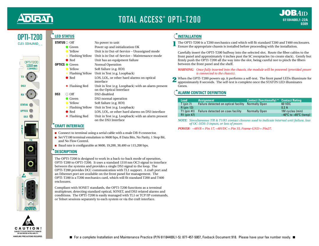
The
Compliant with SONET standards, the
INSTALLATION
1 The
Carefully insert the
WARNING: Once fully inserted into the chassis, the module will be powered (provided power is connected to the chassis).
2 When the
ALARM CONTACT DEFINITION
Lead | Assignment | Contact (functionally) * | Contact Rating |
T (pin 7) | Failure detected on optical facility | Normally Open | 60 VDC |
R (pin 13) |
|
| 0.2 A |
T1 (pin 41) | Failure detected on coax facility | Normally Open | 1M cycles (min) |
R1 (pin 47) |
|
| − 40ºC to +65ºC (temp) |
NOTE: Simultaneous T/R & T1/R1 contact closures used to indicate internal unit failure, loss of
POWER:
C A U T I O N !
SUBJECT TO ELECTROSTATIC DAMAGE
OR DECREASE IN RELIABILITY.
HANDLING PRECAUTIONS REQUIRED. | ■ For a complete Installation and Maintenance Practice (P/N | ■ |
|
