Section
Issue 2, May 2001
CLEI Code # NCM5MPSD_ _
Type 400 Single Mount Housing
For Loop Powered Network Termination Units
Installation and Maintenance
CONTENTS |
|
| ||
1. | GENERAL | 1 | ||
2. | INSTALLATION | 1 | ||
3. | CONNECTIONS | 2 | ||
4. | MAINTENANCE | 3 | ||
5. | WARRANTY AND CUSTOMER SERVICE ... | 3 | ||
FIGURES |
|
| ||
Figure 1. | T400 | LP Housing | 1 | |
Figure 2. | T400 | LP Housing with Cover Open | 2 | |
Figure 3. | T400 | LP Housing Rear Panel | 2 | |
TABLES |
|
|
| |
Table 1. | Cable Pairs | 2 | ||
Table 2. | Barrier Strip Interface Connection to Card |
| ||
|
| Edge Connector | 2 | |
1. GENERAL
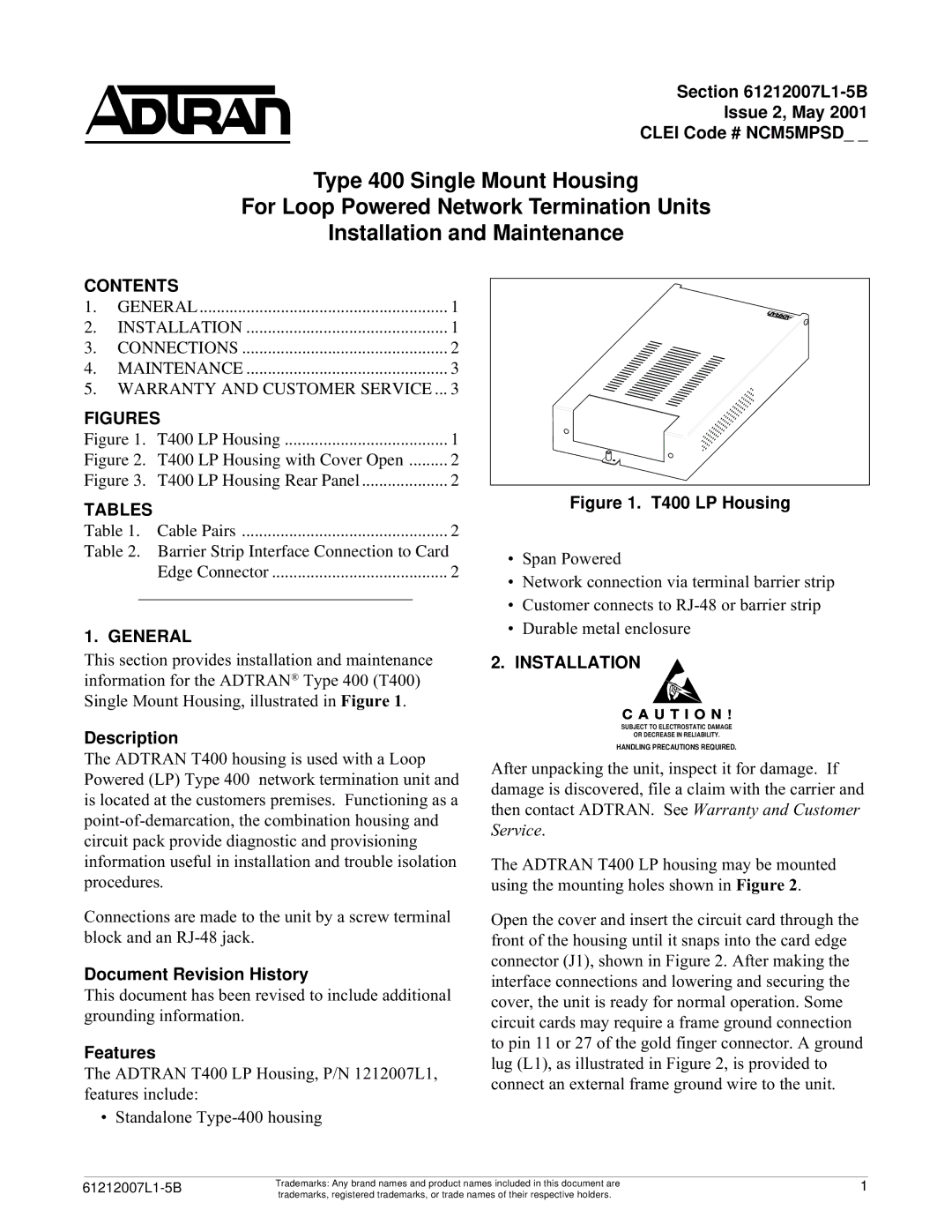
This section provides installation and maintenance information for the ADTRAN® Type 400 (T400) Single Mount Housing, illustrated in Figure 1.
Description
The ADTRAN T400 housing is used with a Loop Powered (LP) Type 400 network termination unit and is located at the customers premises. Functioning as a
Connections are made to the unit by a screw terminal block and an
Document Revision History
This document has been revised to include additional grounding information.
Features
The ADTRAN T400 LP Housing, P/N 1212007L1, features include:
• Standalone
Figure 1. T400 LP Housing
•Span Powered
•Network connection via terminal barrier strip
•Customer connects to
•Durable metal enclosure
2.INSTALLATION
C A U T I O N !
SUBJECT TO ELECTROSTATIC DAMAGE
OR DECREASE IN RELIABILITY.
HANDLING PRECAUTIONS REQUIRED.
After unpacking the unit, inspect it for damage. If damage is discovered, file a claim with the carrier and then contact ADTRAN. See Warranty and Customer Service.
The ADTRAN T400 LP housing may be mounted using the mounting holes shown in Figure 2.
Open the cover and insert the circuit card through the front of the housing until it snaps into the card edge connector (J1), shown in Figure 2. After making the interface connections and lowering and securing the cover, the unit is ready for normal operation. Some circuit cards may require a frame ground connection to pin 11 or 27 of the gold finger connector. A ground lug (L1), as illustrated in Figure 2, is provided to connect an external frame ground wire to the unit.
Trademarks: Any brand names and product names included in this document are | 1 | |
Section | ||
| trademarks, registered trademarks, or trade names of their respective holders. |
|
