8 |
|
|
|
|
|
| 1 |
P1 |
|
|
|
|
|
|
|
DRR | DRT | DTT | DTR | TR | TT | RR | RT |
Modular Connector
|
|
| |
8 7 2 1 |
|
|
|
Terminal | P1 | Frame | L1 |
Barrier |
| Ground | |
Strip |
| Lug |
|
|
|
| |
| J1 |
|
|
| Card Edge |
| |
| Connector |
| |
| Mounting |
| |
| Holes |
|
|
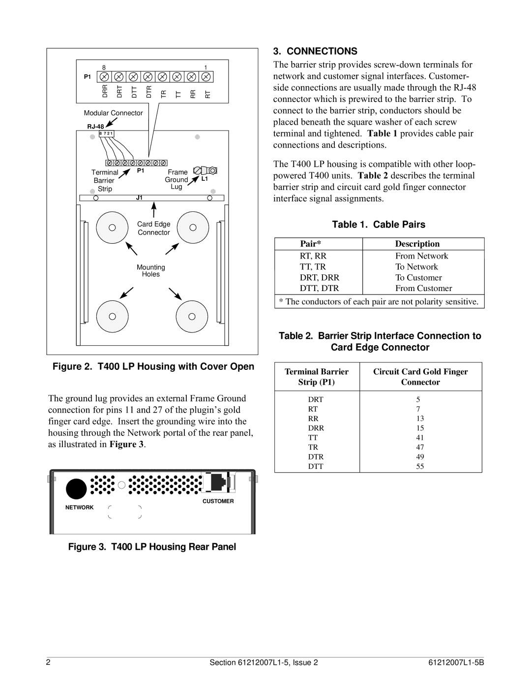
Figure 2. T400 LP Housing with Cover Open
The ground lug provides an external Frame Ground connection for pins 11 and 27 of the plugin’s gold finger card edge. Insert the grounding wire into the housing through the Network portal of the rear panel, as illustrated in Figure 3.
CUSTOMER
NETWORK
Figure 3. T400 LP Housing Rear Panel
3. CONNECTIONS
The barrier strip provides
The T400 LP housing is compatible with other loop- powered T400 units. Table 2 describes the terminal barrier strip and circuit card gold finger connector interface signal assignments.
Table 1. | Cable Pairs | |
|
| |
Pair* |
| Description |
|
|
|
RT, RR |
| From Network |
TT, TR |
| To Network |
DRT, DRR |
| To Customer |
DTT, DTR |
| From Customer |
|
|
|
* The conductors of each pair are not polarity sensitive.
Table 2. Barrier Strip Interface Connection to
Card Edge Connector
Terminal Barrier | Circuit Card Gold Finger |
Strip (P1) | Connector |
|
|
DRT | 5 |
RT | 7 |
RR | 13 |
DRR | 15 |
TT | 41 |
TR | 47 |
DTR | 49 |
DTT | 55 |
|
|
2 | Section |