Manuals
/
Advantech
/
Computer Equipment
/
Network Card
Advantech
user manual
Top View of EKI-2525P
Models:
EKI-2525P
1
20
28
28
Download
28 pages
50.34 Kb
17
18
19
20
21
22
23
24
Troubleshooting
Specifications
Install
LED Indicators
Pin Assignment & Wiring
Warranty
Dimension
Safety Precaution
Safety
Power Connection
Page 20
Image 20
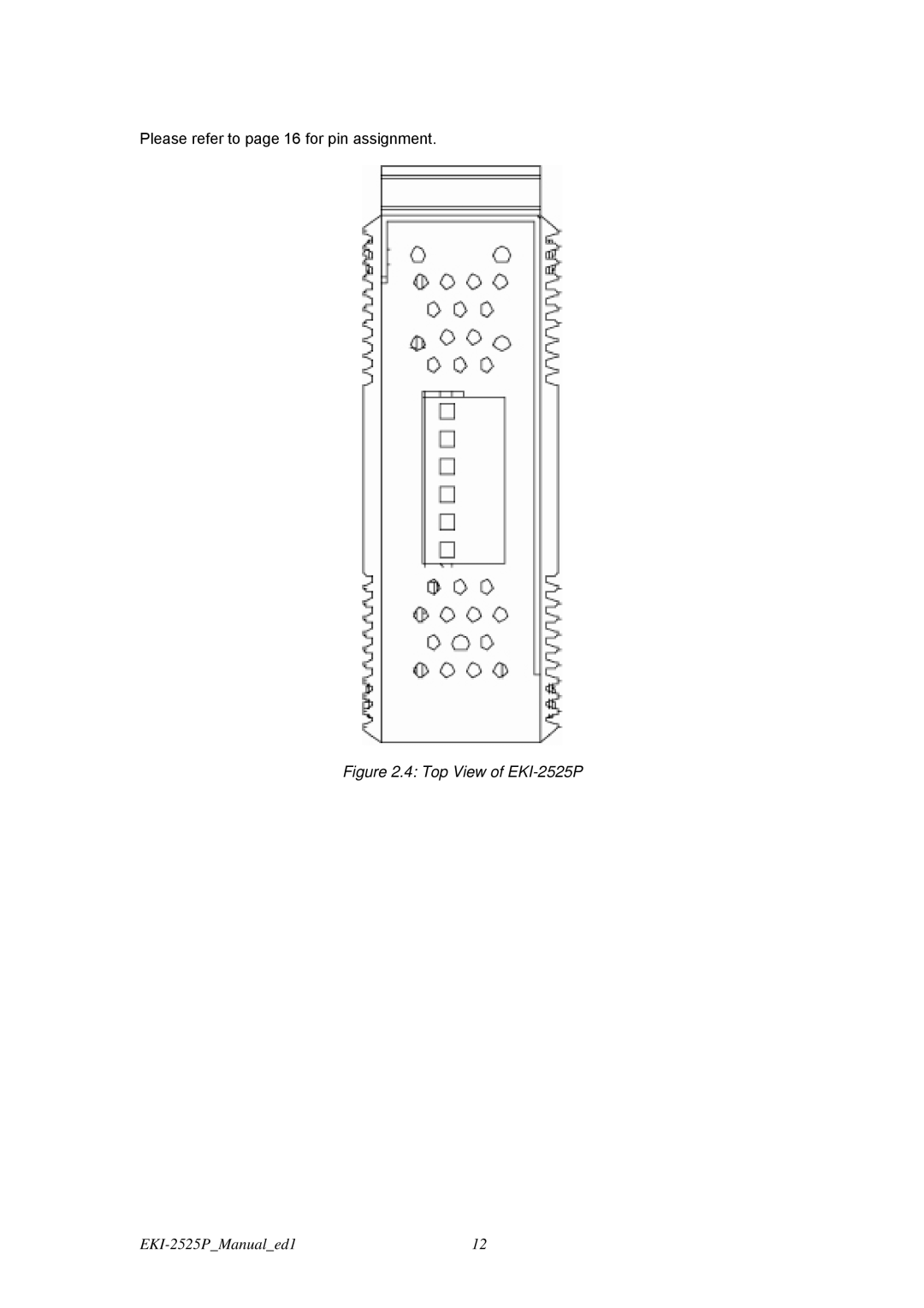
Please refer to page 16 for pin assignment.
Figure 2.4: Top View of
EKI-2525P
EKI-2525P_Manual_ed1
12
Page 19
Page 21
Page 20
Image 20
Page 19
Page 21
Contents
EKI-2525P
Copyright Acknowledgements
Product Warranty 2 years
Declaration of Conformity
FCC Class a Technical Support and Assistance
Safety Instructions
Safety Precaution Static Electricity
Appendix a Pin Assignment & Wiring
Viii
Overview
Introduction
Features
Specification Communications
Power
Interface
Mechanism
Safety
Certifications
Free Fall
Shock
Safety Precaution
Packing List
Installation
Installation
LED Indicators
Dimensions units mm
Front View of EKI-2525P
Side View of EKI-2525P
Rear View of EKI-2525P
Top View of EKI-2525P
Mounting
Wall mounting
Installation to DIN-rail Step
DIN-rail Mounting
Installation to DIN-rail Step
Power Connection
Network Connection
Troubleshooting
Troubleshooting
Pin Assignment & Wiring
Figure A.1 RJ-45 Pin Assignment
Top
Page
Image
Contents