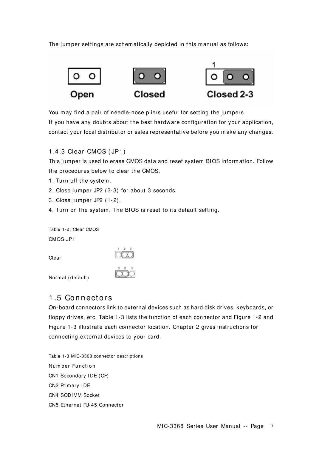
The jumper settings are schematically depicted in this manual as follows:
You may find a pair of
If you have any doubts about the best hardware configuration for your application, contact your local distributor or sales representative before you make any changes.
1.4.3 Clear CMOS (JP1)
This jumper is used to erase CMOS data and reset system BIOS information. Follow the procedures below to clear the CMOS.
1.Turn off the system.
2.Close jumper JP2
3.Close jumper JP2
4.Turn on the system. The BIOS is reset to its default setting.
Table
CMOS JP1
Clear
Normal (default)
1.5 Connectors
Table
Number Function
CN1 Secondary IDE (CF)
CN2 Primary IDE
CN4 SODIMM Socket
CN5 Ethernet