PCE-5120 specifications
The Advantech PCE-5120 is a cutting-edge industrial computer designed for demanding applications in various sectors such as automation, transportation, and manufacturing. It stands out for its robust performance, versatile features, and exceptional reliability, making it an ideal choice for industrial environments.One of the key features of the PCE-5120 is its powerful processing capability. Equipped with the latest Intel processors, it offers impressive computing performance to handle complex tasks and data processing. This capability is essential for applications that require real-time data analysis and decision-making.
The PCE-5120 is built to withstand harsh conditions commonly found in industrial settings. Its rugged design includes an extended temperature range, vibration resistance, and electromagnetic compatibility. This durability ensures that the system operates reliably even in challenging environments, reducing the risk of downtime.
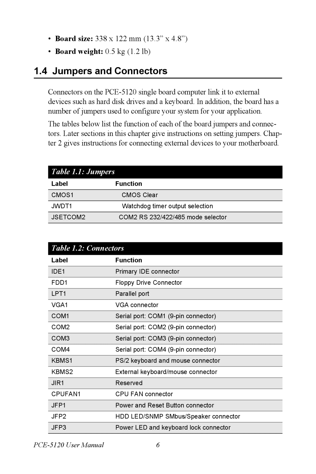
Another notable characteristic of the PCE-5120 is its extensive connectivity options. It supports a variety of interfaces including USB, Ethernet, and serial ports, allowing for seamless integration with different devices and networks. This flexibility enables users to connect various sensors, controllers, and other peripherals, enhancing the system's functionality.
The PCE-5120 also features expandability options through its PCIe and PCI slots. Users can customize the system by adding additional cards for specialized tasks such as additional I/O ports, communication interfaces, or even graphics capabilities. This modular design ensures that the system can be tailored to meet specific application requirements.
In addition to its hardware capabilities, the PCE-5120 is backed by Advantech’s comprehensive software solutions. The system supports various operating systems, including Windows and Linux, providing users with the freedom to choose their preferred platform. Furthermore, Advantech offers a range of software tools for remote management and monitoring, helping users maintain system performance and security.
The PCE-5120 is also designed with energy efficiency in mind. Its advanced power management features help reduce energy consumption, making it not only an environmentally friendly choice but also a cost-effective solution for long-term operations.
In summary, the Advantech PCE-5120 is a powerful and reliable industrial computer that combines robust processing capabilities, extensive connectivity, and excellent durability. With its expandability and software support, it is well-suited for a wide range of industrial applications, making it a valuable asset for businesses looking to enhance their operational efficiency.

