Description of the hob
2
6
4
1
|
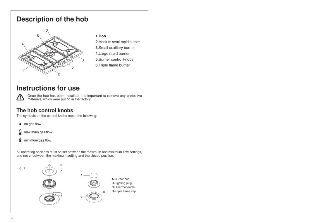
| 1.Hob |
|
| 2.Medium |
|
| 3.Small auxiliary burner |
|
| 4.Large rapid burner |
| 3 | 5.Burner control knobs |
| 6.Triple flame burner | |
5 |
| |
|
|
2
Instructions for use
Once the hob has been installed, it is important to remove any protective materials, which were put on in the factory.
The hob control knobs
The symbols on the control knobs mean the following:
no gas flow
![]() maximum gas flow
maximum gas flow
minimum gas flow
All operating positions must be set between the maximum and minimum flow settings, and never between the maximum setting and the closed position.
D
Fig. 1
A
A
![]() C
C
![]()
![]()
![]()
![]()
![]()
![]()
![]()
![]() BB
BB
| |
| |
| C- Thermocouple |
C |
6