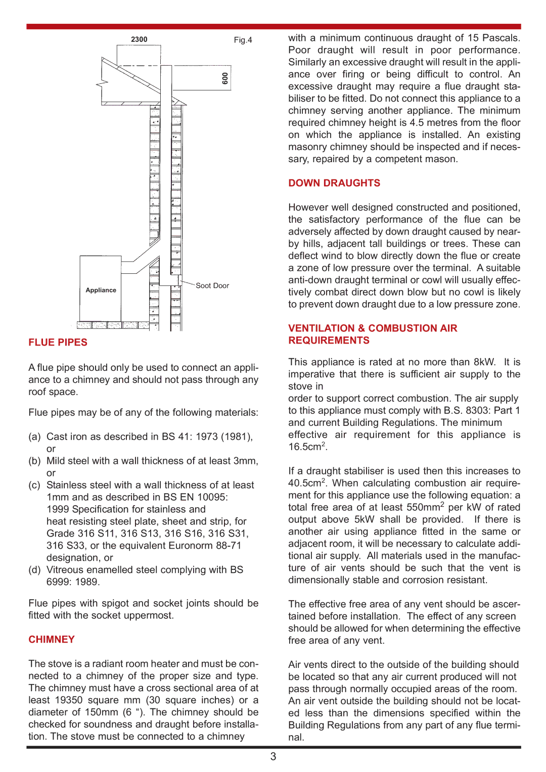
2300Fig.4
with a minimum continuous draught of 15 Pascals. Poor draught will result in poor performance. Similarly an excessive draught will result in the appli-
Appliance
FLUE PIPES
600
Soot Door
ance over firing or being difficult to control. An excessive draught may require a flue draught sta- biliser to be fitted. Do not connect this appliance to a chimney serving another appliance. The minimum required chimney height is 4.5 metres from the floor on which the appliance is installed. An existing masonry chimney should be inspected and if neces- sary, repaired by a competent mason.
DOWN DRAUGHTS
However well designed constructed and positioned, the satisfactory performance of the flue can be adversely affected by down draught caused by near- by hills, adjacent tall buildings or trees. These can deflect wind to blow directly down the flue or create a zone of low pressure over the terminal. A suitable
VENTILATION & COMBUSTION AIR
REQUIREMENTS
A flue pipe should only be used to connect an appli- ance to a chimney and should not pass through any roof space.
Flue pipes may be of any of the following materials:
(a)Cast iron as described in BS 41: 1973 (1981), or
(b)Mild steel with a wall thickness of at least 3mm, or
(c)Stainless steel with a wall thickness of at least 1mm and as described in BS EN 10095: 1999 Specification for stainless and
heat resisting steel plate, sheet and strip, for Grade 316 S11, 316 S13, 316 S16, 316 S31, 316 S33, or the equivalent Euronorm
(d)Vitreous enamelled steel complying with BS 6999: 1989.
Flue pipes with spigot and socket joints should be fitted with the socket uppermost.
CHIMNEY
The stove is a radiant room heater and must be con- nected to a chimney of the proper size and type. The chimney must have a cross sectional area of at least 19350 square mm (30 square inches) or a diameter of 150mm (6 “). The chimney should be checked for soundness and draught before installa- tion. The stove must be connected to a chimney
This appliance is rated at no more than 8kW. It is imperative that there is sufficient air supply to the stove in
order to support correct combustion. The air supply to this appliance must comply with B.S. 8303: Part 1 and current Building Regulations. The minimum effective air requirement for this appliance is 16.5cm2.
If a draught stabiliser is used then this increases to 40.5cm2. When calculating combustion air require- ment for this appliance use the following equation: a total free area of at least 550mm2 per kW of rated output above 5kW shall be provided. If there is another air using appliance fitted in the same or adjacent room, it will be necessary to calculate addi- tional air supply. All materials used in the manufac- ture of air vents should be such that the vent is dimensionally stable and corrosion resistant.
The effective free area of any vent should be ascer- tained before installation. The effect of any screen should be allowed for when determining the effective free area of any vent.
Air vents direct to the outside of the building should be located so that any air current produced will not pass through normally occupied areas of the room. An air vent outside the building should not be locat- ed less than the dimensions specified within the Building Regulations from any part of any flue termi- nal.
3