These air vents must also be fire proofed as per Building Regulations.
Air vents traversing cavity walls should include a continuous duct across the cavity. The duct should be installed in such a manner as not to impair the weather resistance of the cavity. Joints between air vents and outside walls should be sealed to prevent the ingress of moisture. Existing air vents should be of the correct size and unobstructed for the appli- ance in use. If there is an air extraction fan or other air using appliance fitted in the room or adjacent rooms where this appliance is fitted, additional air vents will be required to alleviate the possibility of spillage of products of combustion from the appli- ance/flue while the fan is in operation.
Where such an installation exists, a test for spillage should be made with the fan or fans and other appli- ances using air in operation at full rate, (i.e. extrac- tion fans, tumble dryers) with all external doors and windows closed. If spillage occurs following the above operation, an additional air vent of sufficient size to prevent this occurrence should be installed.
FLUE PIPES
Flue pipes with spigot and socket joints should be fit- ted with the socket upper most. Clearance to com- bustibles must be adhered to when fitting the flue pipe. The flue gas mass flow is 5.4 g/s mineral fuel and 6.1 g/s wood logs. The mean flue gas temper- ature directly downstream of the spigot at nominal heat output is 262°C. The appliance is suitable for continuous operation on solid mineral fuel and inter- mittent operation on wood logs.
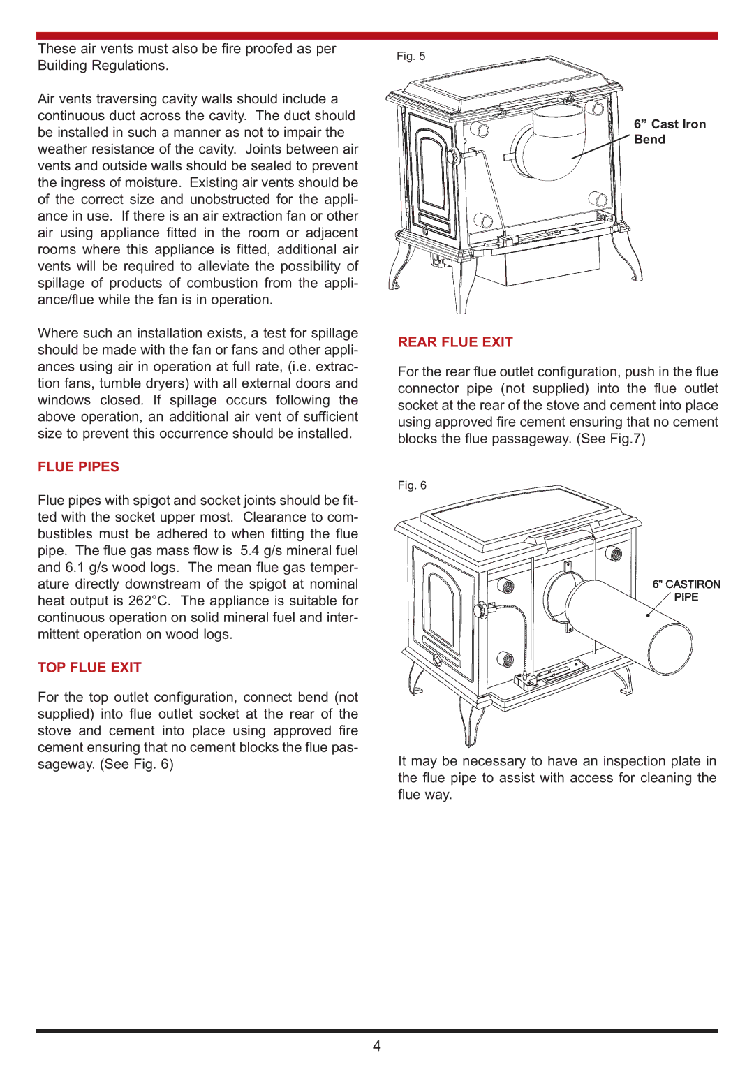
TOP FLUE EXIT
For the top outlet configuration, connect bend (not supplied) into flue outlet socket at the rear of the stove and cement into place using approved fire cement ensuring that no cement blocks the flue pas- sageway. (See Fig. 6)
Fig. 5
6” Cast Iron
![]() Bend
Bend
REAR FLUE EXIT
For the rear flue outlet configuration, push in the flue connector pipe (not supplied) into the flue outlet socket at the rear of the stove and cement into place using approved fire cement ensuring that no cement blocks the flue passageway. (See Fig.7)
Fig. 6
It may be necessary to have an inspection plate in the flue pipe to assist with access for cleaning the flue way.
4