file:///D:/System/DATA/Dx/ds1/Us/iss1/EINS512426/EINS512426.htm
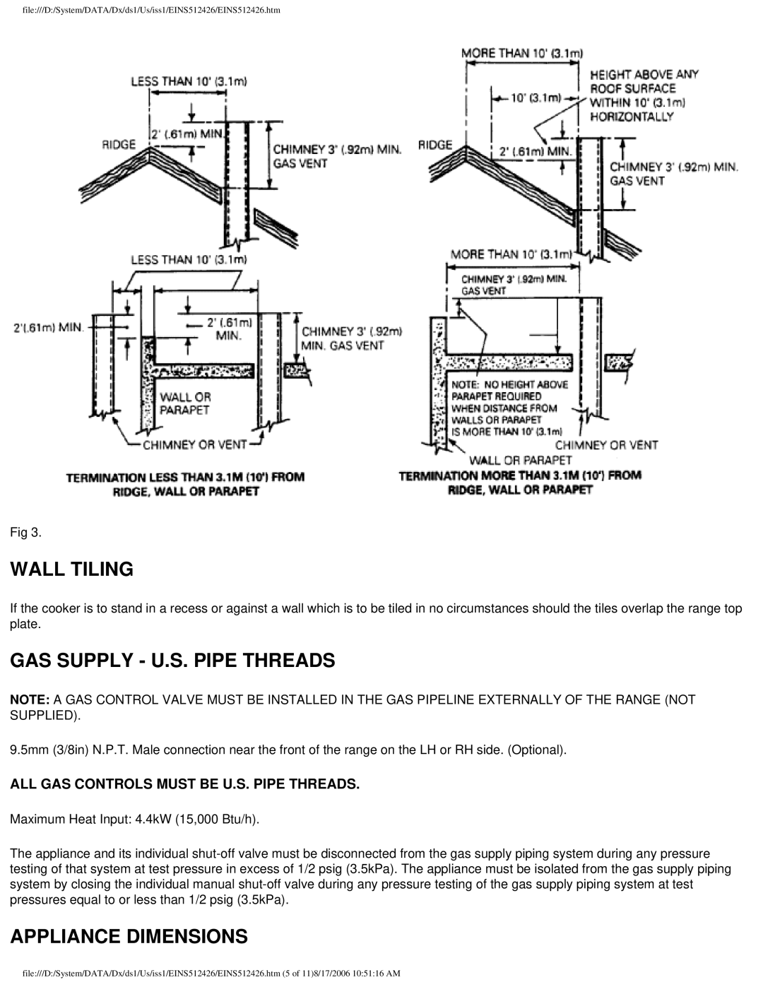
Fig 3.
WALL TILING
If the cooker is to stand in a recess or against a wall which is to be tiled in no circumstances should the tiles overlap the range top plate.
GAS SUPPLY - U.S. PIPE THREADS
NOTE: A GAS CONTROL VALVE MUST BE INSTALLED IN THE GAS PIPELINE EXTERNALLY OF THE RANGE (NOT SUPPLIED).
9.5mm (3/8in) N.P.T. Male connection near the front of the range on the LH or RH side. (Optional).
ALL GAS CONTROLS MUST BE U.S. PIPE THREADS.
Maximum Heat Input: 4.4kW (15,000 Btu/h).
The appliance and its individual
APPLIANCE DIMENSIONS
file:///D:/System/DATA/Dx/ds1/Us/iss1/EINS512426/EINS512426.htm (5 of 11)8/17/2006 10:51:16 AM