Specifications
Specifications
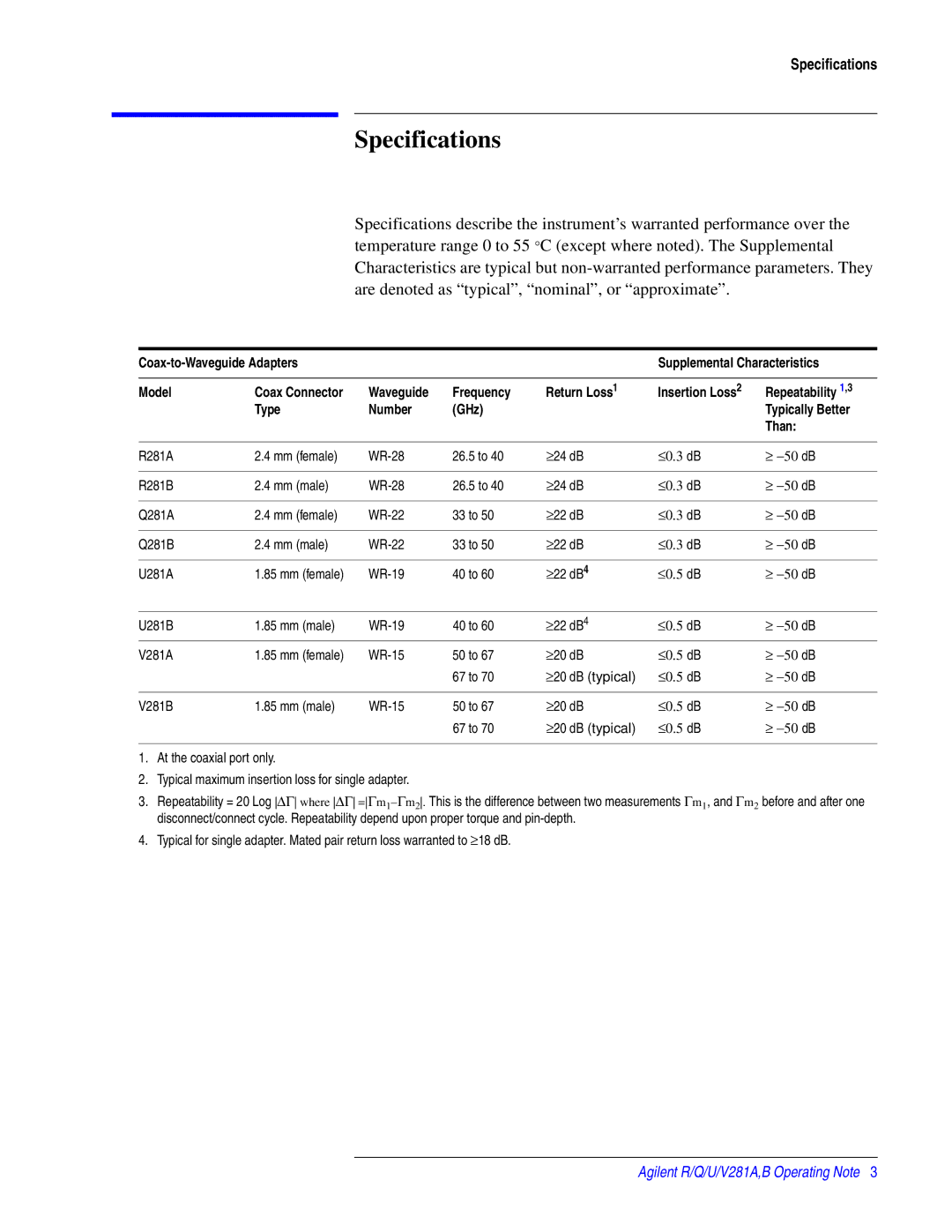
Specifications describe the instrument’s warranted performance over the temperature range 0 to 55 °C (except where noted). The Supplemental Characteristics are typical but
|
|
| Supplemental Characteristics | |||
|
|
|
|
|
|
|
Model | Coax Connector | Waveguide | Frequency | Return Loss1 | Insertion Loss2 | Repeatability 1,3 |
| Type | Number | (GHz) |
|
| Typically Better |
|
|
|
|
|
| Than: |
|
|
|
|
|
|
|
R281A | 2.4 mm (female) | 26.5 to 40 | ≥24 dB | ≤0.3 dB | ≥ −50 dB | |
|
|
|
|
|
|
|
R281B | 2.4 mm (male) | 26.5 to 40 | ≥24 dB | ≤0.3 dB | ≥ −50 dB | |
|
|
|
|
|
|
|
Q281A | 2.4 mm (female) | 33 to 50 | ≥22 dB | ≤0.3 dB | ≥ −50 dB | |
|
|
|
|
|
|
|
Q281B | 2.4 mm (male) | 33 to 50 | ≥22 dB | ≤0.3 dB | ≥ −50 dB | |
|
|
|
|
|
|
|
U281A | 1.85 mm (female) | 40 to 60 | ≥22 dB4 | ≤0.5 dB | ≥ −50 dB | |
|
|
|
|
|
|
|
U281B | 1.85 mm (male) | 40 to 60 | ≥22 dB4 | ≤0.5 dB | ≥ −50 dB | |
V281A | 1.85 mm (female) | 50 to 67 | ≥20 dB | ≤0.5 dB | ≥ −50 dB | |
|
|
| 67 to 70 | ≥20 dB (typical) | ≤0.5 dB | ≥ −50 dB |
|
|
|
|
|
|
|
V281B | 1.85 mm (male) | 50 to 67 | ≥20 dB | ≤0.5 dB | ≥ −50 dB | |
|
|
| 67 to 70 | ≥20 dB (typical) | ≤0.5 dB | ≥ −50 dB |
1.At the coaxial port only.
2.Typical maximum insertion loss for single adapter.
3.Repeatability = 20 Log ∆Γ where ∆Γ
4.Typical for single adapter. Mated pair return loss warranted to ≥18 dB.
Agilent R/Q/U/V281A,B Operating Note 3
