Setting Up a Data Pattern
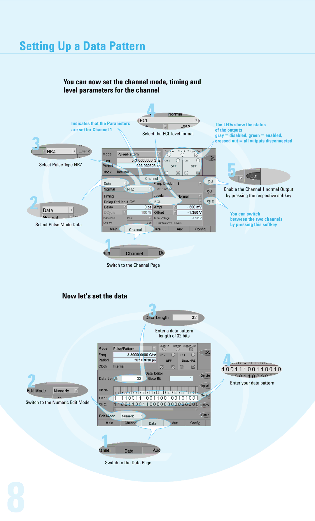
You can now set the channel mode, timing and level parameters for the channel
3
4
Indicates that the Parameters
are set for Channel 1![]()
![]()
![]()
![]()
![]()
![]() Select the ECL level format
Select the ECL level format
The LEDs show the status of the outputs
gray = disabled, green = enabled, crossed out = all outputs disconnected
Select Pulse Type NRZ
2 | - |
| |
| - |
Select Pulse Mode Data |
|
1
Switch to the Channel Page
5![]()
Enable the Channel 1 normal Output by pressing the respective softkey
You can switch
between the two channels by pressing this softkey
Now let’s set the data
3![]()
![]()
![]()
Enter a data pattern
length of 32 bits
4
2 | Enter your data pattern |
| |
Switch to the Numeric Edit Mode |
|
1
Switch to the Data Page
8