Ei261ENRC, Ei261DENRC specifications
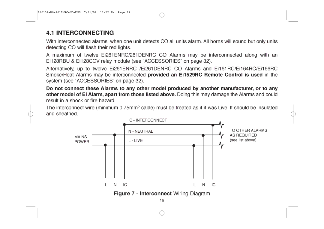
The Aico Ei261DENRC and Ei261ENRC are advanced smoke alarms designed specifically to enhance home safety while providing numerous innovative features. Both models incorporate cutting-edge technologies, ensuring maximum effectiveness and reliability in detecting smoke and fire.The Ei261DENRC is the versatile model that includes a built-in radio interlink feature. This means that when one alarm detects smoke or an increase in temperature, all interconnected units activate simultaneously. As a result, occupants throughout the home are alerted, regardless of their location. This interconnected technology is crucial for large homes or those with multiple levels, as it significantly increases the likelihood that residents will hear the alarm, especially if they are asleep.
In contrast, the Ei261ENRC model does not have the interlink functionality but still boasts a range of important features. Both models utilize a unique high-performance optical sensing technology, which helps in accurately detecting slow-burning fires, commonly associated with smoldering materials. This feature minimizes false alarms, providing peace of mind for homeowners who are often concerned about nuisance activations.
Another standout characteristic of the Ei261DENRC and Ei261ENRC is their long-lasting battery life. Equipped with a lithium battery that can last up to 10 years, users can enjoy the convenience of reduced maintenance. The battery is designed to power the alarm throughout its lifespan, meaning there won’t be any need for frequent replacements.
Moreover, both alarms come with a unique ‘Smart Silence’ feature, allowing homeowners to temporarily silence the alarm with the press of a button during cooking or when dealing with minor smoke occurrences that do not pose a danger. This intelligent feature helps in preventing unnecessary distress caused by false alarms.
Furthermore, these models are designed with a user-friendly installation process in mind, with clear guidelines provided for mounting and setup. Both the Ei261DENRC and Ei261ENRC are compliant with the latest safety standards, ensuring optimal performance and reliability.
Overall, the Aico Ei261DENRC and Ei261ENRC smoke alarms represent an essential investment for any household prioritizing safety and reliability. Their integration of innovative technologies and user-friendly features make them a must-have for modern home protection.

