834168 C P0811JZ specifications
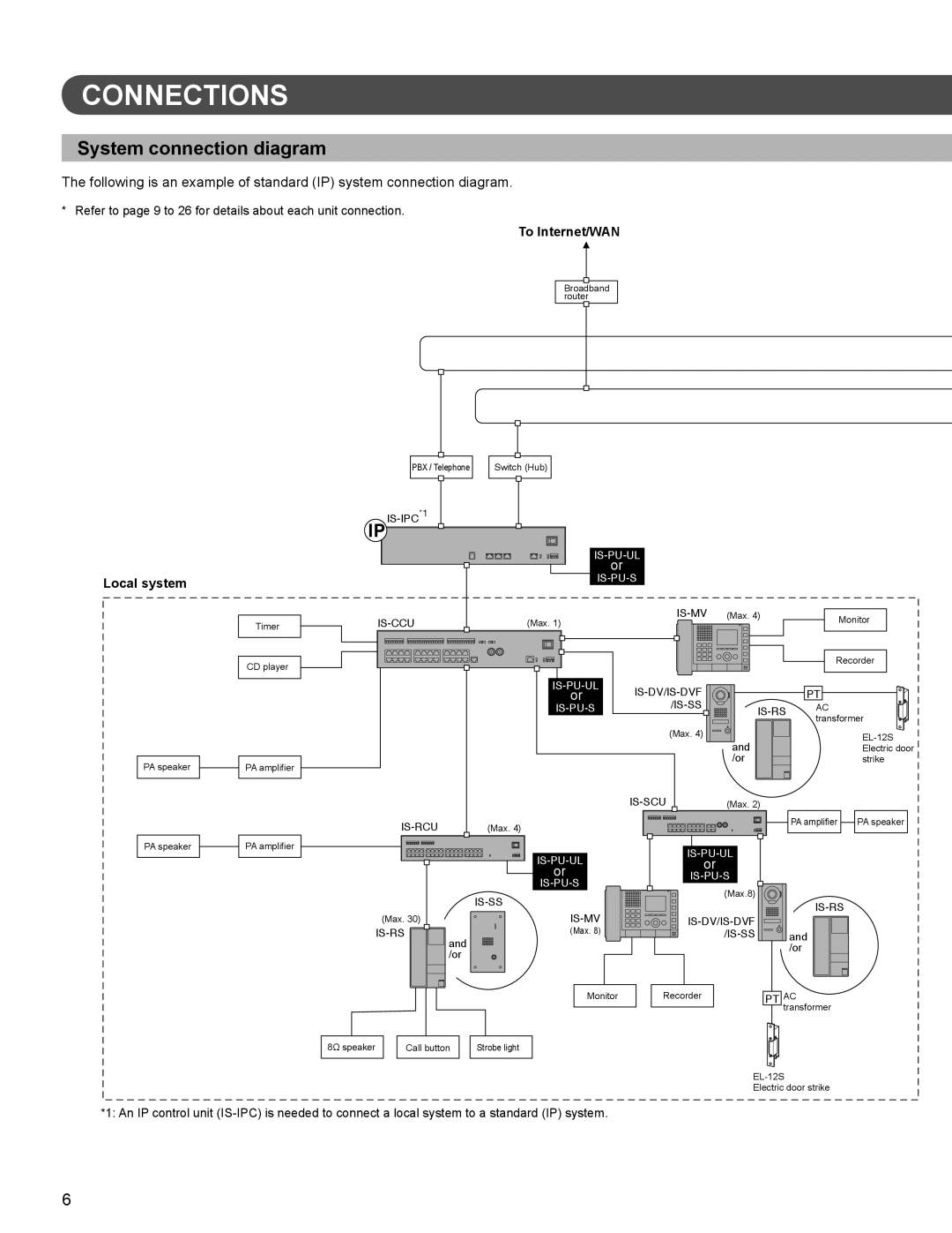
The Aiphone 834168 C P0811JZ is a cutting-edge intercom solution designed to enhance communication and security in a variety of settings. This model is particularly suitable for residential, commercial, and industrial applications, thanks to its robust features and advanced technologies.One of the main characteristics of the Aiphone 834168 C P0811JZ is its user-friendly interface. The system includes a high-resolution display that provides clear visuals for monitoring and communication. The keypad is intuitive, allowing users to easily navigate the functions and access various settings without the need for extensive training.
This model employs advanced digital communication technologies, ensuring high-quality audio transmission. The integrated noise-cancellation feature minimizes background noise, allowing for clearer conversations even in noisy environments. Additionally, the unit supports full-duplex communication, enabling both parties to speak and listen simultaneously, mirroring a natural conversation.
In terms of video capabilities, the Aiphone 834168 C P0811JZ is equipped with a high-definition camera that offers wide-angle views, making it ideal for monitoring entry points and common areas. The night vision functionality enhances security by allowing visibility in low-light conditions, ensuring users can see who is at their door regardless of the time of day.
Another significant feature of this intercom system is its integration capabilities. The Aiphone 834168 C P0811JZ seamlessly connects with various home automation systems, allowing users to control lighting, locks, and other devices directly from the intercom. This integration enhances overall security and convenience, enabling users to manage their environments with ease.
The system also incorporates advanced security features, including encrypted communication protocols that protect against unauthorized access. This ensures that all conversations remain private, providing peace of mind for users concerned about security vulnerabilities.
Durability is another hallmark of the Aiphone 834168 C P0811JZ. Designed for long-term use, the unit is constructed with high-quality materials that withstand the rigors of daily use. This makes it an excellent investment for any setting looking to enhance its communication and security measures.
In conclusion, the Aiphone 834168 C P0811JZ is an exceptional intercom solution that combines usability, advanced technology, and robust security features. Its impressive capabilities make it a valuable option for anyone looking to improve their communication systems, ensuring safety and convenience in any environment.

