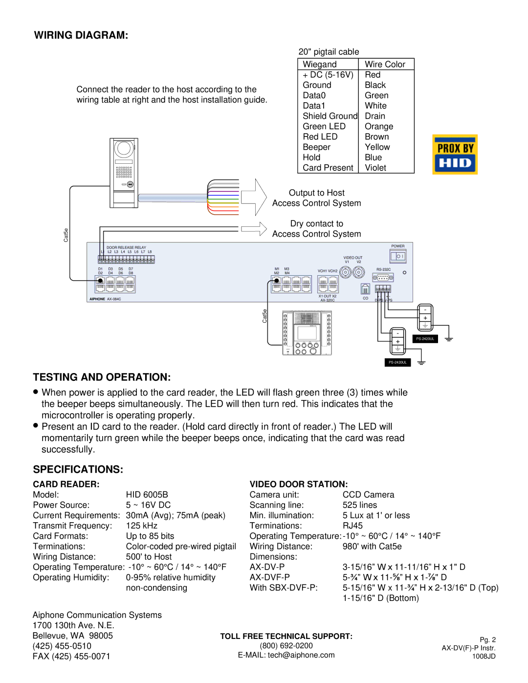
AX-DV(F)-P specifications
The Aiphone AX-DV(F)-P is a versatile and advanced intercom system designed to enhance communication and security in various residential and commercial settings. A standout feature of this unit is its ability to connect seamlessly with other devices in Aiphone's AX series, providing users with a comprehensive communication solution.One of the main features of the AX-DV(F)-P is its high-quality video resolution. The intercom is equipped with a high-definition camera that ensures clear and crisp video footage. This feature allows users to identify visitors easily, enhancing safety and security in any environment. The unit also comes with a built-in speaker and microphone, facilitating two-way communication without significant latency.
The AX-DV(F)-P supports a wide range of technologies, including H.265 video compression. This innovative technology reduces bandwidth usage while maintaining high-quality video output, making it ideal for installations where network capacity may be limited. Additionally, the unit features infrared night vision capabilities, ensuring that users can see visitors even in low-light conditions, further enhancing its functionality.
Another significant aspect of the Aiphone AX-DV(F)-P is its user-friendly interface. The device is equipped with intuitive controls that make it easy for anyone to operate. Users can easily adjust settings, view video feeds, and communicate with visitors without needing extensive technical knowledge. This accessibility makes it an excellent choice for both residential users and businesses seeking an efficient communication solution.
The design of the AX-DV(F)-P is equally impressive, with a sleek and modern appearance that blends well with various architectural styles. The durable construction ensures that the unit can withstand outdoor elements, making it suitable for external installations. Furthermore, its weather-resistant build prevents damage from rain and extreme temperatures.
In conclusion, the Aiphone AX-DV(F)-P intercom system stands out due to its combination of advanced technology, high-quality video capabilities, ease of use, and robust design. Its integration with Aiphone's AX series allows for a fully connected communication environment, making it an ideal choice for both residential and commercial applications. Whether for security monitoring, visitor management, or general communication, the AX-DV(F)-P delivers a reliable and effective solution that meets the needs of today’s users.

