Video Modulator with Audio Door Station and CCTV Interface
- INSTRUCTIONS -
The
|
|
| SENSOR RELAY MASTER | AUDIO |
OUT | IN | NC NC NO NO A1 A2 | 1 2 | |
|
|
| 75 OHM |
|
| VIDEO |
| OFF ON | AIPHONE |
|
|
| ||
|
|
|
| |
TERMINAL DEFINITIONS: |
|
|
| |
AUDIO 1, 2: | ||||
MASTER A1, A2: Output from | ||||
RELAY NO, NO: | Normally Open relay contact, activated when JA monitor is on |
| ||
SENSOR NC, NC: Normally Closed contact, activates unit when tripped by motion detector or other device
| with N/C contacts. (Requires “SET” mode to be active on monitor) |
VIDEO IN: | Composite input signal from CCTV camera |
VIDEO OUT: | Composite output to external CCTV monitor, switcher, DVR, video input on another device |
75 OHM SWITCH: Termination Switch. Set to OFF position when VIDEO OUT is connected to CCTV system. Set to ON position when video output is not used
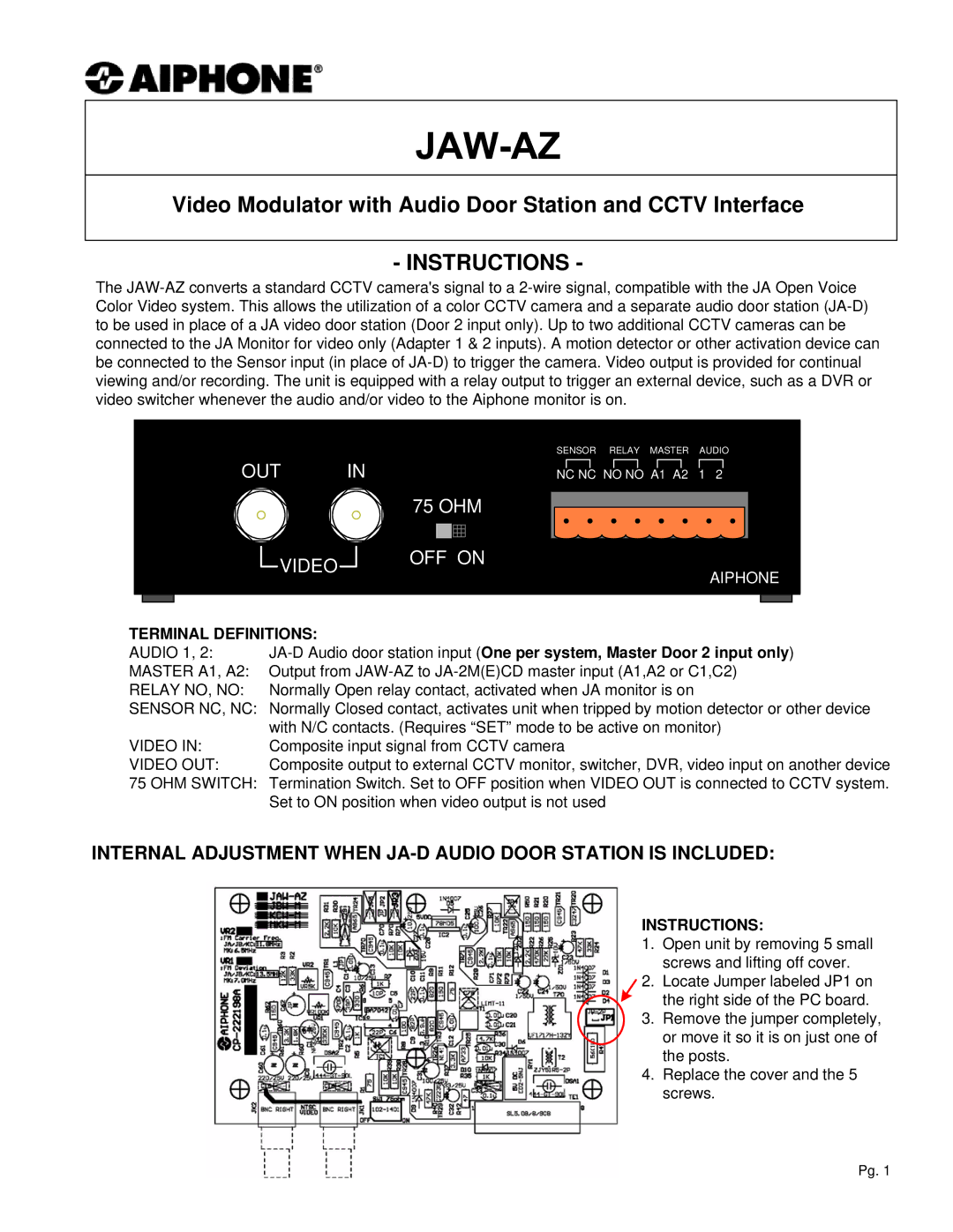
INTERNAL ADJUSTMENT WHEN
INSTRUCTIONS:
1. Open unit by removing 5 small screws and lifting off cover.
2. Locate Jumper labeled JP1 on ![]() the right side of the PC board.
the right side of the PC board.
3. Remove the jumper completely, or move it so it is on just one of the posts.
4. Replace the cover and the 5 screws.
Pg. 1