English
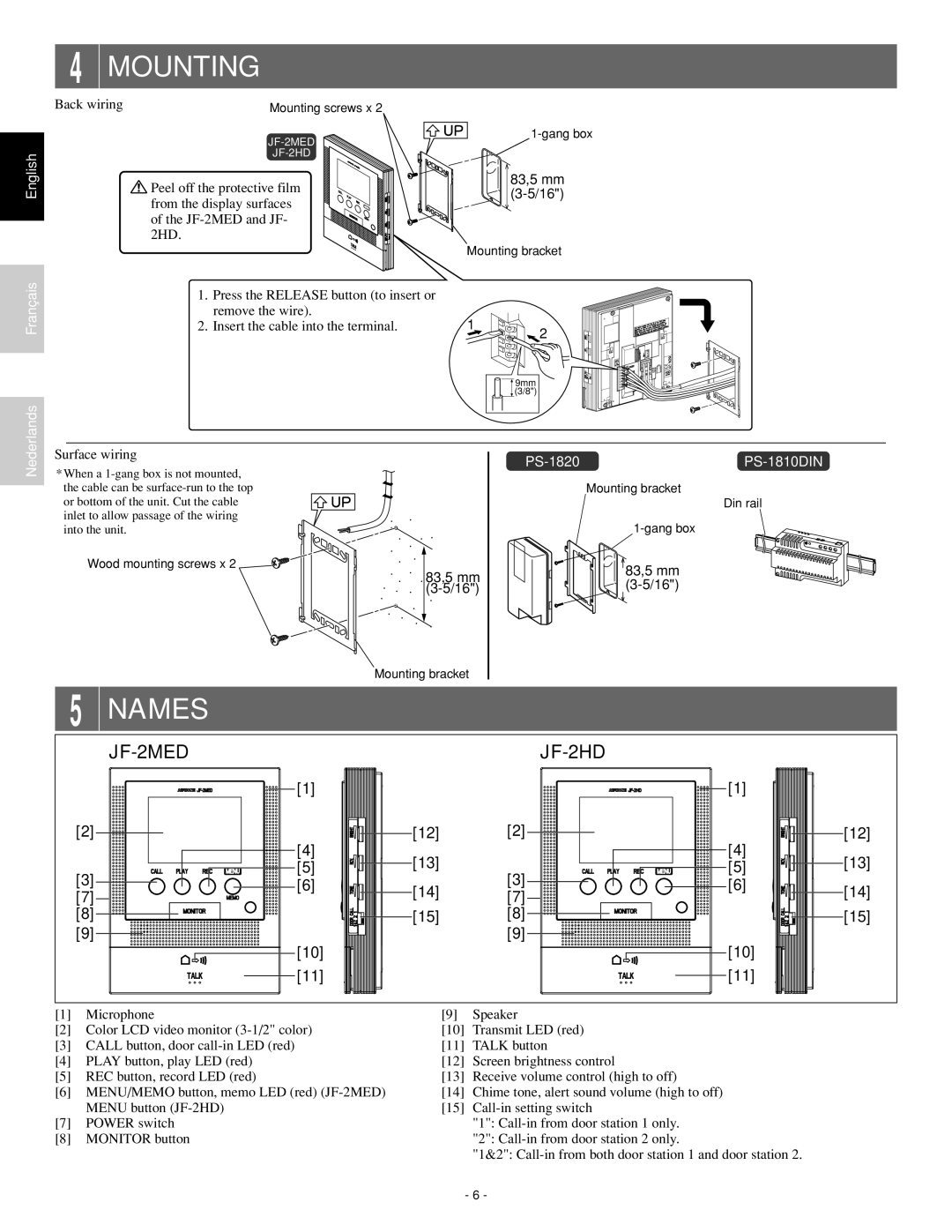
4 MOUNTING
Back wiring | Mounting screws x 2 |
| |
|
![]() Peel off the protective film from the display surfaces of the
Peel off the protective film from the display surfaces of the
83,5 mm
Mounting bracket
Français
1.Press the RELEASE button (to insert or remove the wire).
2. Insert the cable into the terminal. | 1 | 2 |
|
|
![]() 9mm (3/8")
9mm (3/8")
Nederlands
Surface wiring
*When a
Wood mounting screws x 2
83,5 mm
Mounting bracket
Mounting bracket
Din rail
83,5 mm
5 | NAMES |
|
|
|
| |
|
|
|
|
|
| |
| [1] |
|
| [1] |
| |
[2] | [4] | [12] | [2] | [4] | [12] | |
| [13] |
| [13] | |||
[3] | [5] | [3] | [5] | |||
[6] | [14] | [6] | [14] | |||
[7] | [7] | |||||
|
| |||||
[8] |
| [15] | [8] |
| [15] | |
[9] |
|
| [9] |
|
| |
| [10] |
|
| [10] |
| |
| [11] |
|
| [11] |
|
[1]Microphone
[2]Color LCD video monitor
[3]CALL button, door
[4]PLAY button, play LED (red)
[5]REC button, record LED (red)
[6]MENU/MEMO button, memo LED (red)
[7]POWER switch
[8]MONITOR button
[9]Speaker
[10]Transmit LED (red)
[11]TALK button
[12]Screen brightness control
[13]Receive volume control (high to off)
[14]Chime tone, alert sound volume (high to off)
[15]
"1":
"2":
"1&2":
- 6 -