
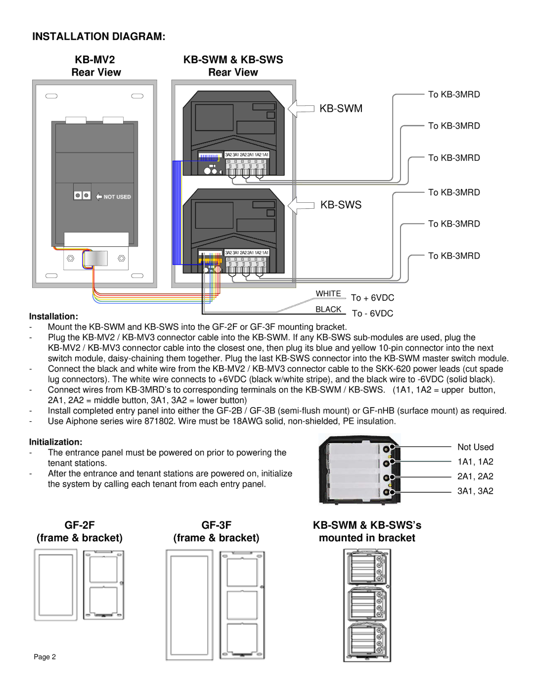
KB-MV2, KB-SWM, KB-MV3, KB-SWS specifications
The Aiphone KB series intercom systems, specifically the KB-MV3, KB-SWS, KB-SWM, and KB-MV2, represent cutting-edge technology designed for residential and commercial communication needs. These models offer a blend of functionality, aesthetic design, and advanced features, making them suitable for a variety of applications.The Aiphone KB-MV3 is a multi-tenant video intercom system that allows users to visually identify visitors through its high-quality video display. It features a 7-inch color LCD screen that provides crisp visuals in real-time. The screen is complemented by an intuitive user interface, making communication straightforward. The system supports up to four interior stations, allowing for communication between various rooms or apartments. It also features a door release function, enabling users to manage access seamlessly.
The KB-SWS model is designed for enhanced versatility. It acts as a supplementary interior station for the KB series, featuring a 7-inch touchscreen for effortless operation. The KB-SWS allows users to initiate calls to the main intercom system, interact with other interior stations, and monitor visitors via its integrated video capabilities. With audio enhancement technology, the KB-SWS ensures clear sound quality, making conversations easy and effective.
The KB-SWM, on the other hand, represents a wireless alternative that caters to users seeking mobility and flexibility. This model is equipped with advanced wireless technology that ensures reliable communication without the need for extensive wiring setups. It offers similar features to the wired models, including video capabilities and door release options, but with the added benefit of portability.
Lastly, the KB-MV2 serves as a compact intercom solution designed for smaller residences or office spaces. This model features a 4-inch color LCD and retains essential intercom capabilities without overwhelming users with complexity. The KB-MV2 focuses on delivering reliable audio and video communication while being user-friendly.
Collectively, the Aiphone KB series showcases advanced intercom technology with robust features like video display, door release functions, and enhanced audio quality. Their design promotes ease of use and effective communication, making them an ideal choice for modern living and working environments. Whether it's the expansive capabilities of the KB-MV3 or the compact efficiency of the KB-MV2, Aiphone continues to innovate to meet the diverse needs of its customers.