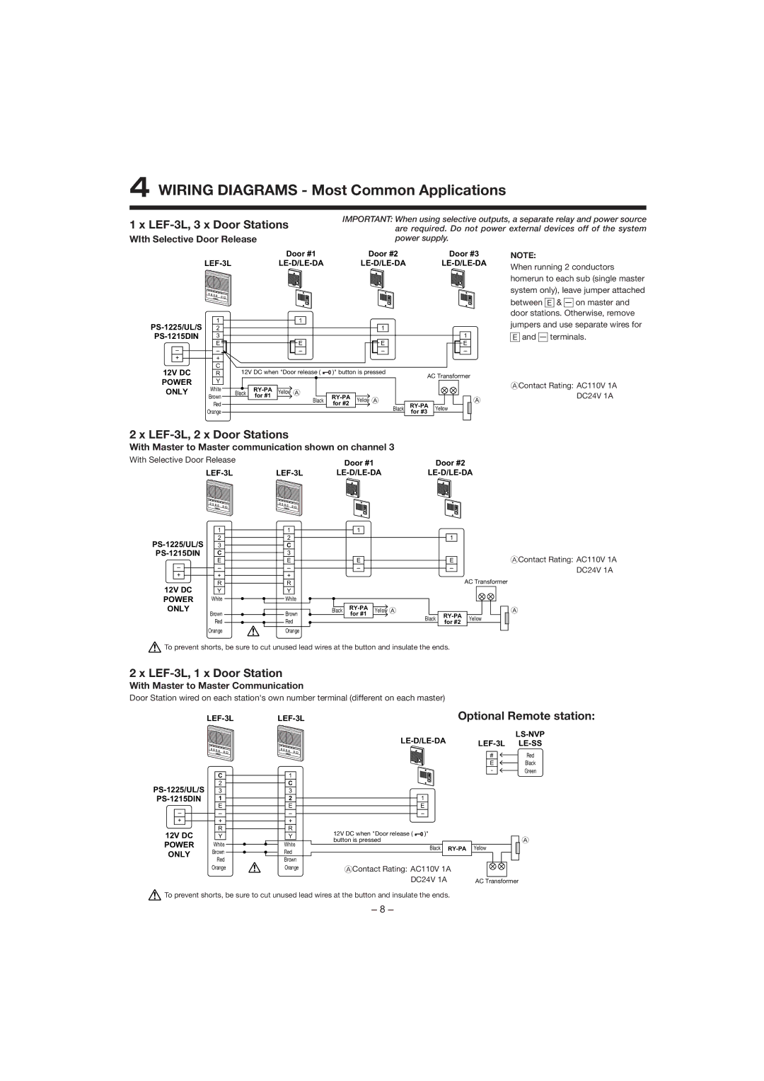
4WIRING DIAGRAMS - Most Common Applications
1 x LEF-3L, 3 x Door Stations
WIth Selective Door Release
Door #1
IMPORTANT: When using selective outputs, a separate relay and power source are required. Do not power external devices off of the system power supply.
Door #2 | Door #3 | NOTE: |
When running 2 conductors | ||
|
| |
|
| homerun to each sub (single master |
|
| system only), leave jumper attached |
|
| between E & — on master and |
|
| door stations. Otherwise, remove |
1 | ||
2 | ||
3 | ||
| E | |
– | – | |
+ | + | |
12V DC | C | |
R | ||
POWER | Y | |
ONLY | White | |
Brown | ||
| ||
| Red | |
| Orange |
1
1
|
| 1 |
E | E | E |
– | – | – |
12V DC when "Door release ( | )" button is pressed |
| AC Transformer | |||||||||||||
|
|
|
|
|
|
|
|
|
|
|
|
|
|
|
|
|
|
|
|
|
|
|
|
|
|
|
|
|
|
|
|
|
|
Black | Yellow A |
|
|
|
|
|
|
|
|
|
|
|
|
| ||
|
| for #1 |
|
|
|
|
|
|
|
|
|
|
|
|
| |
|
| Black | Yellow A |
|
|
|
|
|
|
|
| A | ||||
|
|
| for #2 |
|
|
|
|
|
|
|
| |||||
|
|
|
|
|
|
| Black | Yellow |
|
| ||||||
|
|
|
|
|
|
| for #3 |
|
|
| ||||||
|
|
|
|
|
|
|
|
|
|
|
|
|
|
|
|
|
jumpers and use separate wires for
E and — terminals.
AContact Rating: AC110V 1A DC24V 1A
2 x LEF-3L, 2 x Door Stations
With Master to Master communication shown on channel 3
With Selective Door Release |
| Door #1 | Door #2 |
|
| ||
| 1 |
2 | |
3 | |
C | |
| E |
– | – |
+ | + |
12V DC | R |
Y | |
POWER | White |
ONLY | Brown |
| |
| Red |
| Orange |
1 |
2 |
C |
3 |
E |
– |
+ |
R |
Y |
White |
Brown |
Red |
Orange |
|
|
|
| 1 |
|
|
|
|
|
|
|
|
|
|
|
|
|
|
|
|
|
|
| E |
|
|
|
|
|
|
|
|
| – |
|
|
|
|
|
|
|
|
|
|
|
|
|
|
|
|
|
|
|
|
|
|
|
|
|
|
|
|
|
|
|
| |||
Black |
| Yellow A |
| ||||||
for #1 |
|
| |||||||
|
|
|
|
|
|
| |||
Black
1
EAContact Rating: AC110V 1A
– | DC24V 1A | |
| AC Transformer | |
A | ||
Yellow | ||
for #2 | ||
|
![]() To prevent shorts, be sure to cut unused lead wires at the button and insulate the ends.
To prevent shorts, be sure to cut unused lead wires at the button and insulate the ends.
2 x LEF-3L, 1 x Door Station
With Master to Master Communication
Door Station wired on each station's own number terminal (different on each master)
| C | |
2 | ||
3 | ||
1 | ||
| E | |
– | – | |
+ | + | |
12V DC | R | |
Y | ||
POWER | White | |
ONLY | Brown | |
Red | ||
| ||
| Orange |
1 |
C |
3 |
2 |
E |
– |
+ |
R |
Y |
White |
Red |
Brown |
Orange |
Optional Remote station:
|
|
| |
|
| ||
| |||
| # | Red |
E | Black |
- | Green |
| 1 |
|
|
|
|
|
|
|
|
|
| E |
|
|
|
|
|
|
|
|
|
| – |
|
|
|
|
|
|
|
|
|
12V DC when "Door release ( | )" |
|
|
|
|
|
|
|
| |
button is pressed |
|
|
|
|
|
|
|
|
| A |
|
| Black | Yellow |
|
| |||||
|
|
|
|
|
|
|
|
|
|
|
|
|
|
|
|
|
|
|
|
|
|
|
|
|
|
|
|
|
|
|
|
|
|
|
|
|
|
|
|
|
|
|
|
AContact Rating: AC110V 1A
DC24V 1A | AC Transformer |
![]() To prevent shorts, be sure to cut unused lead wires at the button and insulate the ends.
To prevent shorts, be sure to cut unused lead wires at the button and insulate the ends.
– 8 –