Video Modulator with Audio Door Station and CCTV Interface
- INSTRUCTIONS -
The
|
| SENSOR RELAY MASTER | AUDIO |
OUT | IN | NC NC NO NO A1 A2 | 1 2 |
|
| 75 OHM |
|
VIDEO |
| OFF ON | AIPHONE |
|
| ||
|
|
|
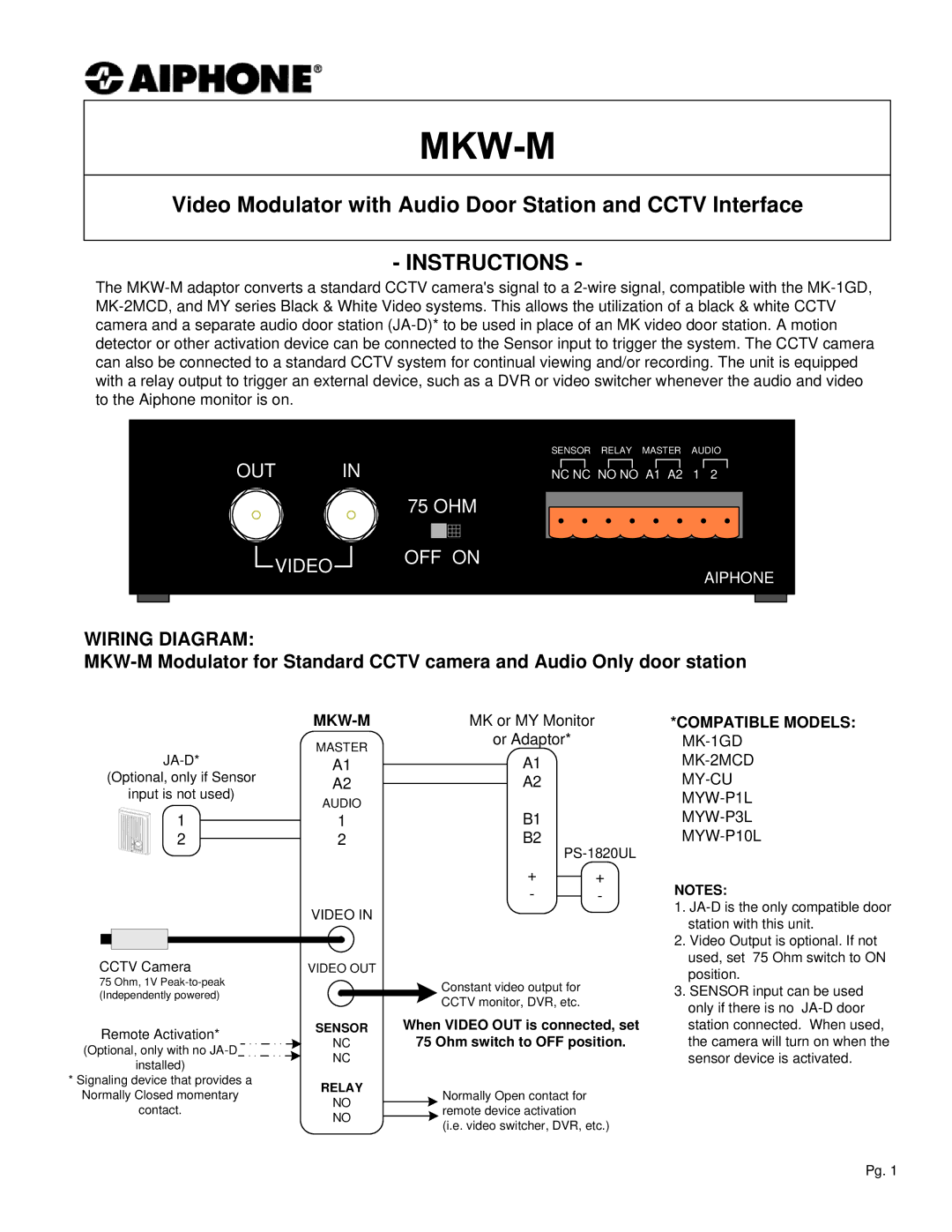
WIRING DIAGRAM:
|
|
| MK or MY Monitor | |||
|
| MASTER | or Adaptor* | |||
| A1 | |||||
|
| A1 |
| |||
(Optional, only if Sensor |
|
| A2 |
| A2 | |
input is not used) | AUDIO |
|
| |||
1 |
|
| B1 | |||
|
| 1 |
| |||
|
| |||||
2 |
|
| 2 |
| B2 | |
|
| |||||
*COMPATIBLE MODELS: MK-1GD
MK-2MCD
MY-CU
MYW-P1L
MYW-P3L
MYW-P10L
+ | + | ||
- |
|
| - |
| |||
VIDEO IN
NOTES:
1. | |
| station with this unit. |
2. | Video Output is optional. If not |
| used, set 75 Ohm switch to ON |
CCTV Camera
75 Ohm, 1V
Remote Activation*
(Optional, only with no ![]() installed)
installed)
*Signaling device that provides a Normally Closed momentary contact.
VIDEO OUT
|
|
|
| Constant video output for |
|
|
|
| CCTV monitor, DVR, etc. |
SENSOR | When VIDEO OUT is connected, set | |||
NC | 75 Ohm switch to OFF position. | |||
NC |
|
|
| |
RELAY |
|
| Normally Open contact for | |
NO |
|
| ||
|
| remote device activation | ||
NO |
|
| ||
|
| (i.e. video switcher, DVR, etc.) | ||
|
|
|
| |
position. |
3. SENSOR input can be used |
only if there is no |
station connected. When used, |
the camera will turn on when the |
sensor device is activated. |
Pg. 1