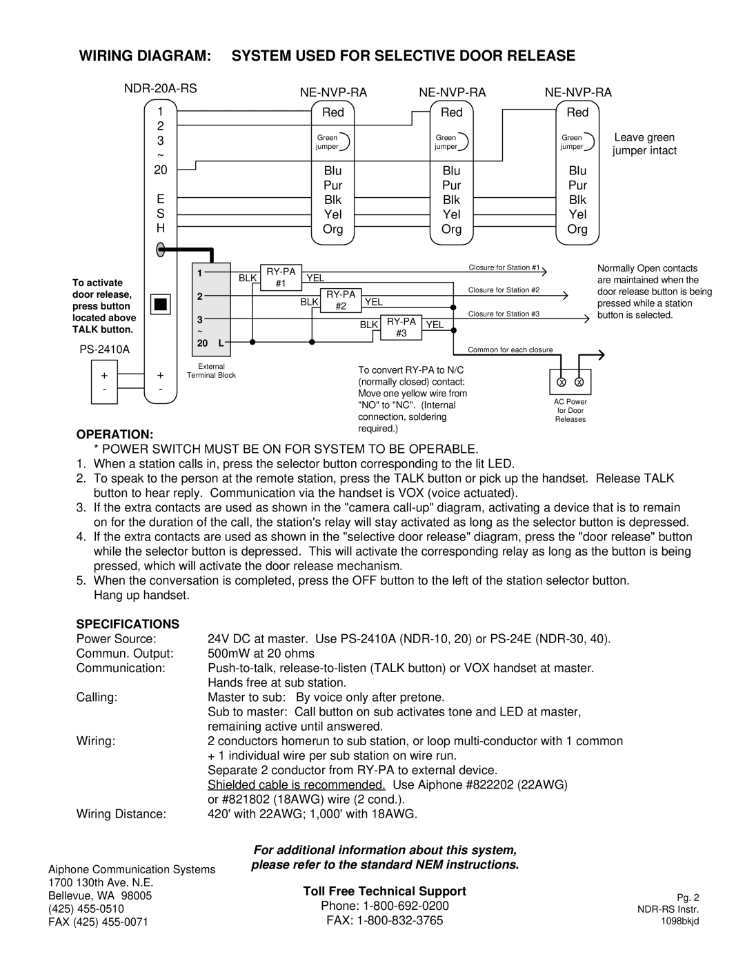
WIRING DIAGRAM: SYSTEM USED FOR SELECTIVE DOOR RELEASE
|
|
| ||
|
| |||
1 | Red | Red | Red |
|
2 |
|
|
| Leave green |
3 | Green | Green | Green | |
~ | jumper | jumper | jumper | jumper intact |
|
|
| ||
|
|
|
| |
20 | Blu | Blu | Blu |
|
E | Pur | Pur | Pur |
|
Blk | Blk | Blk |
| |
S | Yel | Yel | Yel |
|
H | Org | Org | Org |
|
To activate door release, press button located above TALK button.
| |||
|
|
| + |
| + |
| |
| |||
| - |
| - |
| |||
|
|
|
|
1 | BLK | YEL |
|
|
| Closure for Station #1 | Normally Open contacts | |
|
|
|
| are maintained when the | ||||
| #1 |
|
|
|
| |||
|
|
|
|
|
| Closure for Station #2 | door release button is being | |
2 |
|
| BLK | YEL |
| |||
|
|
|
| pressed while a station | ||||
|
|
| #2 |
|
| |||
|
|
|
|
|
| Closure for Station #3 | button is selected. | |
3 |
|
|
|
|
| |||
|
|
|
| BLK | YEL |
| ||
~ |
|
|
|
|
| #3 |
|
|
20 | L |
|
|
|
|
| Common for each closure |
|
|
|
|
|
|
|
|
| |
External |
|
|
|
|
|
|
| |
Terminal Block |
|
|
|
|
| x | x | |
|
|
|
|
|
|
| ||
|
|
|
|
|
|
| AC Power | |
|
|
|
|
|
|
| for Door | |
|
|
|
|
|
|
| Releases | |
OPERATION:
*POWER SWITCH MUST BE ON FOR SYSTEM TO BE OPERABLE.
1.When a station calls in, press the selector button corresponding to the lit LED.
2.To speak to the person at the remote station, press the TALK button or pick up the handset. Release TALK button to hear reply. Communication via the handset is VOX (voice actuated).
3.If the extra contacts are used as shown in the "camera
4.If the extra contacts are used as shown in the "selective door release" diagram, press the "door release" button while the selector button is depressed. This will activate the corresponding relay as long as the button is being pressed, which will activate the door release mechanism.
5.When the conversation is completed, press the OFF button to the left of the station selector button. Hang up handset.
SPECIFICATIONS |
|
Power Source: | 24V DC at master. Use |
Commun. Output: | 500mW at 20 ohms |
Communication: | |
| Hands free at sub station. |
Calling: | Master to sub: By voice only after pretone. |
| Sub to master: Call button on sub activates tone and LED at master, |
| remaining active until answered. |
Wiring: | 2 conductors homerun to sub station, or loop |
| + 1 individual wire per sub station on wire run. |
| Separate 2 conductor from |
| Shielded cable is recommended. Use Aiphone #822202 (22AWG) |
| or #821802 (18AWG) wire (2 cond.). |
Wiring Distance: | 420' with 22AWG; 1,000' with 18AWG. |
Aiphone Communication Systems
1700 130th Ave. N.E.
Bellevue, WA 98005
(425)
For additional information about this system, please refer to the standard NEM instructions.
Toll Free Technical Support
Phone:
FAX:
Pg. 2
1098bkjd