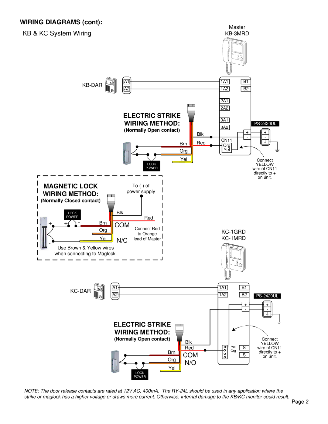
WIRING DIAGRAMS (cont): | Master | |
KB & KC System Wiring | ||
A1![]()
![]() 1A1
1A1
A2![]()
![]() 1A2
1A2
2A1
B1
B2
ELECTRIC STRIKE
WIRING METHOD:
(Normally Open contact)
Brn
Org
Yel
|
| LOCK |
|
| POWER |
MAGNETIC LOCK |
| To |
WIRING METHOD: |
| power supply |
|
|
2A2
3A1
3A2
Blk
Red CN11
Org
Yel
+ | + |
- | - |
Connect
YELLOW
wire of CN11
directly to +
on unit.
(Normally Closed contact) |
|
| ||||
|
| LOCK |
| Blk |
| |
| POWER |
|
| Red | ||
+ | + | - | Brn |
| ||
COM Connect Red | ||||||
|
|
| Org | |||
|
|
| Yel |
| to Orange | |
- |
|
| N/C | lead of Master | ||
|
|
|
| |||
|
|
|
|
| ||
Use Brown & Yellow wires when connecting to Maglock.
A1
A2
ELECTRIC STRIKE |
|
|
|
|
| ||||||||
|
|
|
|
| |||||||||
WIRING METHOD: |
|
|
|
|
| ||||||||
|
|
|
|
| |||||||||
(Normally Open contact) |
| Blk |
| ||||||||||
|
|
|
|
|
|
|
|
|
|
|
|
| |
|
|
|
|
|
|
|
| Brn |
|
| Red |
| |
|
|
|
|
|
|
|
|
| COM |
| |||
|
|
|
|
|
|
|
| Org |
| ||||
|
|
|
|
|
|
|
|
| N/O |
| |||
|
|
|
|
|
|
|
|
|
|
|
|
| |
|
|
|
|
|
|
|
| Yel |
| ||||
|
|
|
|
|
|
|
|
|
|
| |||
|
| LOCK |
|
|
|
|
|
|
|
|
| ||
|
| POWER |
|
|
|
|
|
|
|
|
| ||
|
|
|
|
|
|
|
|
|
|
|
|
|
|
1A1 | B1 |
|
1A2 | B2 | |
|
| |
| + | + |
| - | - |
|
| Connect |
Yel | S | YELLOW |
wire of CN11 | ||
Org | S | directly to + |
| ||
| on unit. | |
|
|
NOTE: The door release contacts are rated at 12V AC, 400mA. The
Page 2