![]()
![]() n
n![]()
Master Station with Selective Door Release
|
|
- SUPPLEMENT TO TC-M INSTRUCTIONS -
The
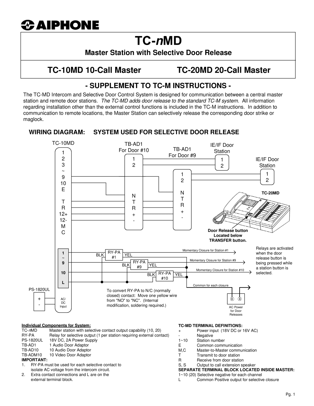
WIRING DIAGRAM: SYSTEM USED FOR SELECTIVE DOOR RELEASE
1
2
3
~
9
10
E
T
R
12+
12-
M
C
|
| IE/IF Door |
|
|
| |||||||
For Door #10 |
| Station |
|
|
| |||||||
1 |
|
| For Door #9 |
| 1 | IE/IF Door | ||||||
|
|
|
|
|
| |||||||
2 |
|
|
|
|
|
|
| 2 | Station | |||
|
|
|
|
|
|
| ||||||
|
|
|
| 1 |
|
|
|
|
| 1 | ||
|
|
|
|
|
|
|
|
| ||||
|
|
|
| 2 |
|
|
|
|
| 2 | ||
|
|
|
|
|
|
|
|
| ||||
| N |
| N |
|
|
|
| |||||
|
|
|
|
|
| |||||||
|
| T |
|
|
|
|
|
| ||||
| T |
|
|
|
|
|
|
| ||||
|
| R |
|
|
|
|
|
| ||||
| R |
|
|
|
|
|
|
| ||||
| + |
|
|
|
|
|
|
| ||||
+ |
|
|
|
|
|
|
|
|
| |||
|
| - |
|
|
|
|
|
|
| |||
- |
|
|
|
|
|
|
|
|
| |||
|
|
|
|
|
|
|
|
|
|
| ||
|
|
|
|
|
|
| Door Release button |
|
|
| ||
|
|
|
|
|
|
| Located below |
|
|
| ||
|
|
|
|
|
|
| TRANSFER button. |
|
|
| ||
+
-
1
~
9
10
L
AC/
DC
Input
BLK |
| YEL |
|
| Momentary Closure for Station #1 | |||||||||
|
|
|
|
|
| |||||||||
|
| #1 |
|
|
|
|
|
|
|
|
|
| Momentary Closure for Station #9 | |
|
|
|
|
|
|
|
|
|
|
|
| |||
|
|
| BLK | YEL |
|
|
|
|
| |||||
|
|
|
|
|
| #9 |
|
|
|
|
|
| Momentary Closure for Station #10 | |
|
|
|
|
|
|
|
|
|
| |||||
|
|
|
|
|
|
|
|
|
|
|
|
| ||
|
|
|
|
|
| BLK |
| YEL |
| |||||
|
|
|
|
|
|
|
|
|
| #10 |
|
| Common for each closure | |
|
|
|
|
|
|
|
|
|
|
|
|
| ||
|
|
|
|
|
|
|
|
|
|
|
|
| ||
|
| To convert |
|
|
|
| ||||||||
|
| closed) contact: Move one yellow wire |
|
|
| |||||||||
|
|
|
| x x | ||||||||||
|
| from "NO" to "NC". (Internal |
|
|
|
| ||||||||
|
|
|
|
|
|
| ||||||||
|
| modification, soldering required.) |
|
|
|
| ||||||||
|
|
|
|
| AC Power | |||||||||
|
|
|
|
|
|
|
|
|
|
|
|
|
| |
|
|
|
|
|
|
|
|
|
|
|
|
|
| for Door |
|
|
|
|
|
|
|
|
|
|
|
|
|
| Releases |
Relays are activated when the door release button is being pressed while a station button is selected.
Individual Components for System: |
| ||
Master station with selective contact output capability (10, 20) | + | Power input (18V DC or 16V AC) | |
Relay for selective output (1 per station requiring external contact) | - | Negative | |
18V DC, 2A Power Supply | 1~10 | Station number | |
1 Audio Door Adaptor | E | Common communication | |
10 Audio Door Adaptor | M,C | ||
| 10 Video Door Adaptor | T | Transmit to door station |
IMPORTANT: |
| R | Receive from door station |
1. | S, S | Output to call extension speaker | |
isolate AC voltage from the intercom circuit. | SEPARATE TERMINAL BLOCK LOCATED INSIDE MASTER: | ||
2. Extra contact connections and L are on the | 1~10 (20) Selective negative for each channel | ||
external terminal block. | L | Common Positive output for selective closure | |
Pg. 1