MODELO 4TM63C/9420C
| | | | | | | 26 |
| | | | | | | 27 |
| | | | | | | 16 |
| | | | | | 14 | 17 |
| | | | | | 12 | |
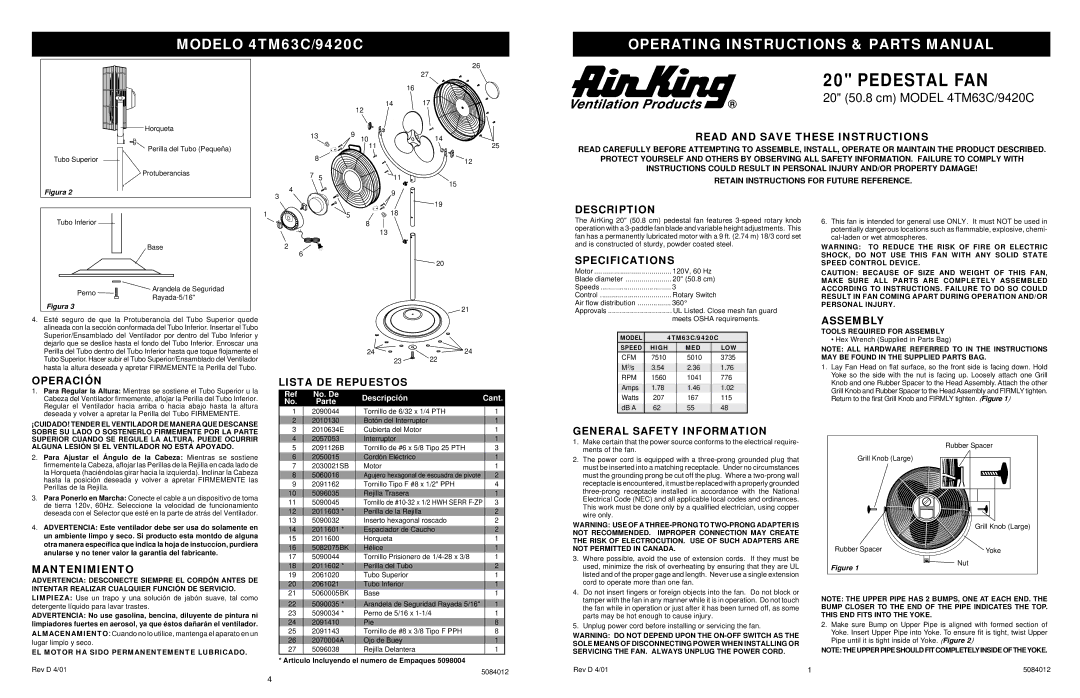
Horqueta | | | | 13 | 9 | | |
| | | | 10 | 14 |
| | | | | |
Perilla del Tubo (Pequeña) | | | | | | 11 | 25 |
| | | | | | |
Tubo Superior | | | | | 8 | | 12 |
| | | | | | |
Protuberancias | | | | 7 | 5 | | 11 |
| | | | |
Figura 2 | | | 4 | | | 15 |
3 | | | | 9 |
| | | | |
| | | | | | 19 |
| | | | | | |
1 | 0 | 3 | 2 | 1 | 5 | | 18 |
OPERATING INSTRUCTIONS & PARTS MANUAL
20" PEDESTAL FAN
20" (50.8 cm) MODEL 4TM63C/9420C
READ AND SAVE THESE INSTRUCTIONS
READ CAREFULLY BEFORE ATTEMPTING TO ASSEMBLE, INSTALL, OPERATE OR MAINTAIN THE PRODUCT DESCRIBED.
PROTECT YOURSELF AND OTHERS BY OBSERVING ALL SAFETY INFORMATION. FAILURE TO COMPLY WITH
INSTRUCTIONS COULD RESULT IN PERSONAL INJURY AND/OR PROPERTY DAMAGE!
RETAIN INSTRUCTIONS FOR FUTURE REFERENCE.
DESCRIPTION
Tubo Inferior | | 8 |
| | 13 |
| Base | 2 |
| | 6 |
| | 20 |
Perno | Arandela de Seguridad | |
Rayada-5/16" | |
| |
Figura 3 | | 21 |
| |
4.Esté seguro de que la Protuberancia del Tubo Superior quede alineada con la sección conformada del Tubo Inferior. Insertar el Tubo
Superior/Ensamblado del Ventilador por dentro del Tubo In | ferior y | |
dejarlo que se deslice hasta el fondo del Tubo Inferior. Enroscar una | | |
Perilla del Tubo dentro del Tubo Inferior | hasta que toque flojamente el | 24 | 24 |
Tubo Superior. Hacer subir el T | ubo Superior/Ensamblado del Ventilador | 23 | 22 |
hasta la altura deseada y apretar FIRMEMENTE la Perilla del Tubo.
The AirKing 20" (50.8 cm) pedestal fan features 3-speed rotary knob operation with a 3-paddle fan blade and variable height adjustments. This fan has a permanently lubricated motor with a 9 ft. (2.74 m) 18/3 cord set and is constructed of sturdy, powder coated steel.
SPECIFICATIONS
Motor | 120V, 60 Hz | |
Blade diameter | 20" (50.8 cm) | |
Speeds | 3 | |
Control | Rotary Switch | |
Air flow distribution | 360 | ° | |
Approvals | UL Listed. Close mesh fan guard |
| | | meets OSHA requirements. |
| | |
| MODEL | 4TM63C/9420C |
| SPEED | HIGH | MED | LOW |
| CFM | 7510 | 5010 | 3735 |
| | | | |
| M 3 /s | 3.54 | 2.36 | 1.76 |
6.This fan is intended for general use ONLY. It must NOT be used in potentially dangerous locations such as flammable, explosive, chemi- cal-laden or wet atmospheres.
WARNING: TO REDUCE THE RISK OF FIRE OR ELECTRIC
SHOCK, DO NOT USE THIS FAN WITH ANY SOLID STATE
SPEED CONTROL DEVICE.
CAUTION: BECAUSE OF SIZE AND WEIGHT OF THIS FAN,
MAKE SURE ALL PARTS ARE COMPLETELY ASSEMBLED
ACCORDING TO INSTRUCTIONS. FAILURE TO DO SO COULD
RESULT IN FAN COMING APART DURING OPERATION AND/OR
PERSONAL INJURY.
ASSEMBLY
TOOLS REQUIRED FOR ASSEMBLY
• Hex Wrench (Supplied in Parts Bag)
NOTE: ALL HARDWARE REFERRED TO IN THE INSTRUCTIONS
MAY BE FOUND IN THE SUPPLIED PARTS BAG.
1. Lay Fan Head on flat surface, so the front side is facing down. Hold |
Yoke so the side with the nut is facing up. Loosely attach one Grill |
¡CUIDADO! TENDER EL VENTILADOR DE MANERA QUE DESCANSE SOBRE SU LADO O SOSTENERLO FIRMEMENTE POR LA PARTE SUPERIOR CUANDO SE REGULE LA ALTURA. PUEDE OCURRIR ALGUNA LESIÓN SI EL VENTILADOR NO ESTÁ APOYADO.
2. Para Ajustar el Ángulo de la Cabeza: Mientras se sostiene
firmemente la Cabeza, aflojar las Perillas de la Rejilla en cada lado de la Horqueta (haciéndolas girar hacia la izquierda). Inclinar la Cabeza hasta la posición deseada y volver a apretar FIRMEMENTE las Perillas de la Rejilla.
3.Para Ponerlo en Marcha: Conecte el cable a un dispositivo de toma de tierra 120v, 60Hz. Seleccione la velocidad de funcionamiento
deseada con el Selector que esté en la parte de atrás del Ventilador.
4.ADVERTENCIA: Este ventilador debe ser usa do solamente en
un ambiente limpo y seco. Si producto esta montdo de alguna
otra manera específica que indica la hoja de instuccíon, purdiera anularse y no tener valor la garantia del fabricante.
MANTENIMIENTO
ADVERTENCIA: DESCONECTE SIEMPRE EL CORDÓN ANTES DE
INTENTAR REALIZAR CUALQUIER FUNCIÓN DE SERVICIO.
LIMPIEZA: Use un trapo y una solución de jabón suave, tal como detergente líquido para lavar trastes.
ADVERTENCIA: No use gasolina, bencina, diluyente de pintura ni limpiadores fuertes en aerosol, ya que éstos dañarán el ventilador.
ALMACENAMIENTO:Cuando no lo utilice, mantenga el aparato en un
lugar limpio y seco.
EL MOTOR HA SIDO PERMANENTEMENTE LUBRICADO.
3 | 2010634E | Cubierta del Motor | | | 1 |
4 | 2057053 | | Interruptor | | | 1 |
5 | 2091126B | Tornillo de #6 x 5/8 Tipo 25 PTH | | 3 | |
6 | 2050015 | | Cordón Eléctrico | | | 1 |
7 | 2030021SB | Motor | | | 1 |
8 | 5060016 | | Agujero hexagonal de escuadra de pivote | | 2 |
9 | 2091162 | Tornillo Tipo F #8 x 1/2" PPH | | | 4 |
10 | 5096035 | | Rejilla Trasera | | | 1 |
11 | 5090045 | | Tornillo de #10-32 x 1/2 HWH SERR F-ZP | 3 |
12 | 2011603 * | Perilla de la Rejilla | | | 2 |
13 | 5090032 | | Inserto hexagonal roscado | | 2 | |
| | | | | |
14 | 2011601 * | Espaciador de Caucho | | 2 | |
15 | 2011600 | | Horqueta | | | 1 |
16 | 5082075BK | Hélice | | | 1 |
17 | 5090044 | | Tornillo Prisionero de 1/4-28 x 3/8 | | 1 | |
| | | | | |
18 | 2011602 * | Perilla del Tubo | | | 2 |
19 | 2061020 | | Tubo Superior | | | 1 |
20 | 2061021 | | Tubo Inferior | | | 1 |
21 | 5060005BK | Base | | | 1 |
| | | | | | |
22 | 5090035 | * | Arandela de Seguridad Rayada 5/16" | 1 | | |
23 | 5090034 | * | Perno de 5/16 x 1-1/4 | | | 1 |
24 | 2091410 | | Pie | | | 8 |
25 | 2091143 | | Tornillo de #8 x 3/8 Tipo F PPH | | | 8 |
26 | 2070004A | | Ojo de Buey | | | 1 |
27 | 5096038 | | Rejilla Delantera | | | 1 |
* Articulo Incluyendo el numero de Empaques 5098004
GENERAL SAFETY INFORMATION
1.Make certain that the power source conforms to the electrical require- ments of the fan.
2.The power cord is equipped with a three-prong grounded plug that must be inserted into a matching receptacle. Under no circumstances must the grounding prong be cut off the plug. Where a two-prong wall receptacle is encountered, it must be replaced with a properly grounded three-prong receptacle installed in accordance with the National Electrical Code (NEC) and all applicable local codes and ordinances.
This work must be done only by a qualified electrician, using copper wire only.
WARNING: USE OF A THREE-PRONG TO TWO-PRONG ADAPTER IS
NOT RECOMMENDED. IMPROPER CONNECTION MAY CREATE
THE RISK OF ELECTROCUTION. USE OF SUCH ADAPTERS ARE
NOT PERMITTED IN CANADA.
3.Where possible, avoid the use of extension cords. If they must be used, minimize the risk of overheating by ensuring that they are UL listed and of the proper gage and length. Never use a single extension
cord to operate more than one fan.
4.Do not insert fingers or foreign objects into the fan. Do not block or tamper with the fan in any manner while it is in operation. Do not touch the fan while in operation or just after it has been turned off, as some parts may be hot enough to cause injury.
5.Unplug power cord before installing or servicing the fan.
WARNING: DO NOT DEPEND UPON THE ON-OFF SWITCH AS THE
SOLE MEANS OF DISCONNECTING POWER WHEN INSTALLING OR
SERVICING THE FAN. ALWAYS UNPLUG THE POWER CORD.
Rubber Spacer
Grill Knob (Large)
| Grill Knob (Large) |
Rubber Spacer | Yoke |
Figure 1 | Nut |
|
NOTE: THE UPPER PIPE HAS 2 BUMPS, ONE AT EACH END. THE |
BUMP CLOSER TO THE END OF THE PIPE INDICATES | THE TOP. |
THIS END FITS INTO THE YOKE. | |
2. Make sure Bump on Upper Pipe is aligned with formed section of Yoke. Insert Upper Pipe into Yoke. To ensure fit is tight, twist Upper
Pipe until it is tight inside of Yoke. | (Figure 2 | ) |
NOTE: THE UPPER PIPE SHOULD FIT COMPLETELY INSIDE OF THEYOKE. | | |