MODELO 4TM61C/9020C
OPERATING INSTRUCTIONS & PARTS MANUAL
ADVERTENCIA: EL CABLE DE SOPORTE SECUNDARIO QUE SE PROPORCIONA DEBE SER USADO PARA SEGURIDAD ADICIONAL.
CABLE DE SOPORTE SECUNDARIO
1. Forme un lazo con el extremo del cable alrededor de la Horqueta. | (Figura 5) |
2.Coloque una Grapa de Cable con la "U" en la cola del lazo, dejando una cola de aproximadamente 1 a 2 pulgadas. Apriete las tuercas de la grapa
a un esfuerzo de torsión de 32
Asegúrese que ninguna parte del cable interfiera con la hélice. | (Figura 5) |
3.Envuelva el otro extremo del cable alrededor de una viga o armadura segura del edificio, o de otro soporte cerca del Ventilador. Si ninguno de
ellos está disponible, envuelva el cable alrededor de la ménsula. (Figura 4) Recoja las partes sobrantes del cable.
ADVERTENCIA: USE SOLAMENTE LOS ELEMENTOS DE MONTAJE RECOMENDADOS PARA ESTE VENTILADOR.
4.Coloque la Grapa de Cable restante, tal como se indica en el paso 2. El exceso de la cola debe ser cortado de modo que se extienda 1 a 2 pulgadas más allá de la Grapa.
5.Verifique el conjunto para asegurar que la hélice esté libre de cualquier obstrucción.
6.Enchufe el cable de conexión eléctrica dentro de un tomacorriente de tres hojas conectado ampropiadamente a tierra. La unidad está lista para funcionar.
ADVERTENCIA: EL USO DEL CABLE DE SOPORTE SECUNDARIO NO
GARANTIZA LA PROTECCIÓN CONTRA LESIONES PERSONALES; EL
MONTAJE TANTO DEL CIRCULADOR COMO DEL CABLE PODRÍA
FALLAR SI SE LO SOMETE A ABUSOS, NEGLIGENCIA O INSTALACIÓN
NO APROPIADA.
OPERACIÓN
20" WALLMOUNT FAN
20" (50.8 cm) MODEL 4TM61C/9020C
READ AND SAVE THESE INSTRUCTIONS
READ CAREFULLY BEFORE ATTEMPTING TO ASSEMBLE, INSTALL, OPERATE OR MAINTAIN THE PRODUCT DESCRIBED. PROTECT
YOURSELF AND OTHERS BY OBSERVING ALL SAFETY INFORMATION. FAILURE TO COMPLY WITH
INSTRUCTIONS COULD RESULT IN PERSONAL INJURY AND/OR PROPERTY DAMAGE!
RETAIN INSTRUCTIONS FOR FUTURE REFERENCE.
Figura 4
Cable de Soporte ![]() Secundario
Secundario
Figura 5
Cola de 1"-2"
Lazo Firme en el Cable
Horqueta
1.Conecte el cable y seleccione la velocidad de funcionamiento deseada con el cordón accionador.
2.ADVERTENCIA:Este ventilador debe ser usa do solmente en unambiente limpio y seco. Si producto esta montado de alguna otra manera espec´ifica que indica la hoja de instrucción, purdiera anularse y no tener valor la garantia del fabricante
MANTENIMIENTO
ADVERTENCIA: DESCONECTE SIEMPRE EL CORDÓN ANTES DE
INTENTAR REALIZAR CUALQUIER FUNCIÓN DE SERVICIO.
LIMPIEZA: Use un trapo y una solución de jabón suave, tal como detergente líquido para lavar trastes.
ADVERTENCIA: No use gasolina, bencina, diluyente de pintura ni limpiadores fuertes en aerosol, ya que éstos dañarán el ventilador. ALMACENAMIENTO: Cuando no lo utilice, mantenga el aparato en un
lugar limpio y seco.
EL MOTOR HA SIDO PERMANENTEMENTE LUBRICADO.
LISTA DE REPUESTOS
DESCRIPTION |
|
|
| Commercial Style fan | |
The AirKing 20" (50.8 cm) wallmount fan features | WARNING | |
operation and a | : This fan should be used only in a | |
motor with a 9 ft. (2.74 m) 18/3 cord set and is constructed of sturdy, | clean, dry environment. Mounting of this product | |
powder coated steel. | in any way other than specified in the instruction | |
SPECIFICATIONS | sheet will null and void the manufacturers warranty. | |
Motor | 120V, 50/60 Hz |
|
|
| |||
Blade diameter | 20" (50.8 cm) |
|
| WARNING: BECAUSE OF SIZE AND WEIGHT OF THIS FAN, MAKE | |||
Speeds | 3 |
|
|
| SURE ALL PARTS ARE COMPLETELY ASSEMBLED ACCORDING TO | ||
Control | Pull Cord |
|
| INSTRUCTIONS. FAILURE TO DO SO COULD RESULT IN FAN COMING | |||
Air flow distribution | 360 | ° |
|
| APART DURING OPERATION AND/OR PERSONAL INJURY. | ||
Approvals | UL Listed. Close mesh fan guard | WALL/CEILING BRACKET INSTALLATION | |||||
|
|
| meets OSHA requirements. | ||||
|
|
| NOTE:ALWAYSINSTALLTHEBRACKETTOAMINIMUMOF2X4STUDDING. | ||||
|
|
|
|
|
|
| |
| MODEL | 4TM61C/9020C |
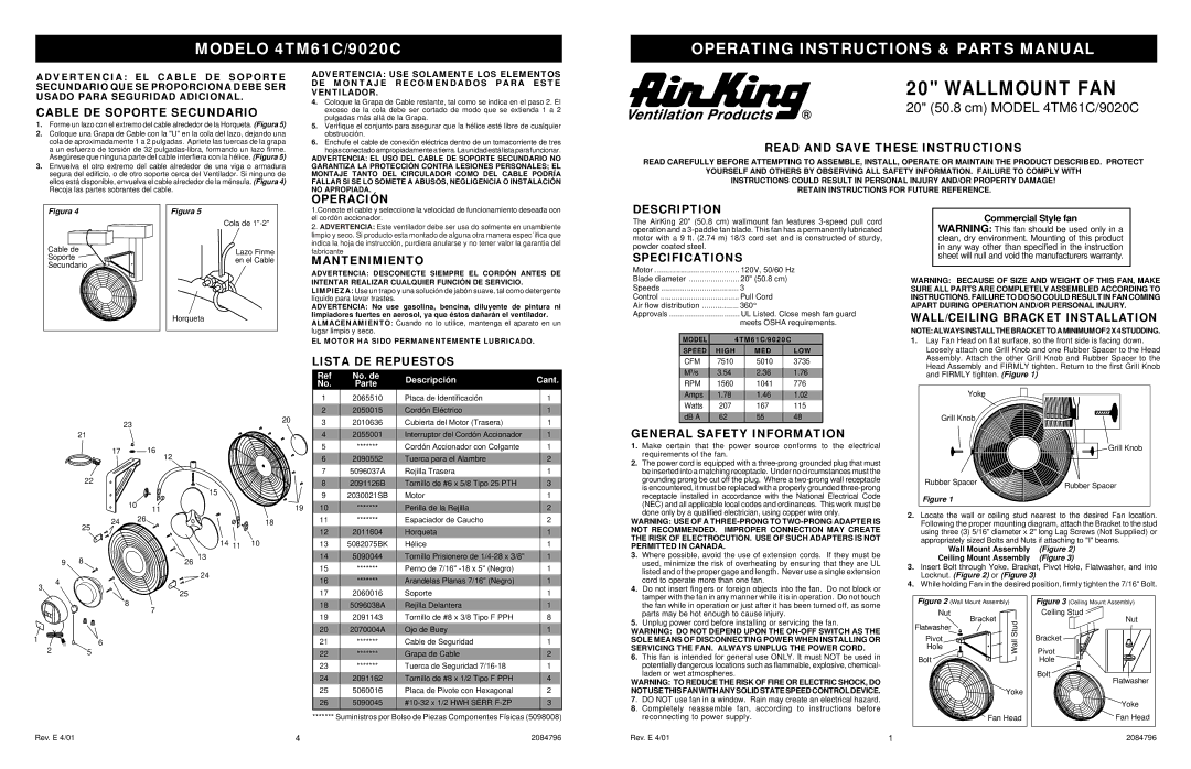
| 1. Lay Fan Head on flat surface, so the front side is facing down. | |||
| SPEED | HIGH | MED | LOW |
| Loosely attach one Grill Knob and one Rubber Spacer to the Head | |
| CFM | 7510 | 5010 | 3735 |
|
| Assembly. Attach the other Grill Knob and Rubber Spacer to the |
|
|
| Head Assembly and FIRMLY tighten. Return to the first Grill Knob | ||||
|
|
|
|
|
|
| |
| M | 3/s | 3.54 | 2.36 | 1.76 |
| |
|
|
| |||||
3
|
| 23 |
|
|
|
| 20 |
|
|
|
|
|
|
| |
| 21 |
|
|
|
|
|
|
| 17 |
| 16 | 12 |
|
|
|
|
|
|
|
|
|
| |
| 22 |
|
|
|
|
|
|
|
|
|
|
| 15 |
|
|
|
| 10 | 11 |
|
|
| 19 |
|
|
|
|
|
| ||
| 24 |
| 26 |
|
|
| 18 |
|
|
|
|
|
| ||
| 25 |
|
|
|
|
|
|
|
|
|
|
| 14 | 11 | 10 |
|
|
|
|
|
|
| |
9 | 8 |
|
| 26 | 13 |
|
|
|
|
|
|
| |||
|
|
|
|
| 24 |
|
|
4
25
8
7
Ref | No. de | Descripción | Cant. | ||
No. | Parte | ||||
|
|
| |||
1 | 2065510 | Placa de Identificación | 1 |
| |
|
|
|
|
| |
2 | 2050015 | Cordón Eléctrico | 1 |
| |
3 | 2010636 | Cubierta del Motor (Trasera) | 1 |
| |
|
|
|
|
| |
4 | 2055001 | Interruptor del Cordón Accionador | 1 |
| |
5 | ******* | Cordón Accionador con Colgante | 1 |
| |
|
|
|
|
| |
6 | 2090552 | Tuerca para el Alambre | 2 |
| |
7 | 5096037A | Rejilla Trasera | 1 |
| |
|
|
|
|
| |
8 | 2091126B | Tornillo de #6 x 5/8 Tipo 25 PTH | 3 |
| |
9 | 2030021SB | Motor | 1 |
| |
|
|
|
|
| |
10 | ******* | Perilla de la Rejilla |
| 2 | |
11 | ******* | Espaciador de Caucho | 2 |
| |
|
|
|
|
| |
12 | 2011604 | Horqueta | 1 |
| |
13 | 5082075BK | Hélice | 1 |
| |
|
|
|
|
| |
14 | 5090044 | Tornillo Prisionero de | 1 |
| |
15 | ******* | Perno de 7/16" | 1 |
| |
|
|
|
|
| |
16 | ******* | Arandelas Planas 7/16" (Negro) | 1 |
| |
17 | 2060016 | Soporte | 1 |
| |
|
|
|
|
| |
18 | 5096038A | Rejilla Delantera | 1 |
| |
19 | 2091143 | Tornillo de #8 x 3/8 Tipo F PPH | 8 |
| |
|
|
|
|
| |
20 | 2070004A | Ojo de Buey | 1 |
| |
|
|
|
| and FIRMLY tighten. (Figure 1) |
RPM | 1560 | 1041 | 776 |
|
Amps | 1.78 | 1.46 | 1.02 | Yoke |
Watts | 207 | 167 | 115 |
|
dB A | 62 | 55 | 48 | Grill Knob |
GENERAL SAFETY INFORMATION |
| |||
1. Make certain that the power source | conforms to the electrical | Grill Knob | ||
requirements of the fan. |
|
|
|
|
2.The power cord is equipped with a
grounding prong be cut off the plug. Where a |
| Rubber Spacer |
|
| Rubber Spacer | |||
is encountered, it must be replaced with a properly grounded |
|
|
| |||||
|
|
|
| |||||
receptacle | installed in accordance with the National Electrical Code |
| Figure 1 |
|
|
|
| |
(NEC) and all applicable local codes and ordinances. This work must be |
|
|
|
|
| |||
|
|
|
|
|
| |||
done only by a qualified electrician, using copper wire only. | 2. Locate the wall or ceiling stud nearest to the desired Fan location. | |||||||
WARNING: USE OF A | ||||||||
| Following the proper mounting diagram, att | ach the Bracket to the stud | ||||||
NOT RECOMMENDED. | IMPROPER CONNECTION MAY CREATE |
| using three (3) 5/16" diameter x 2" long Lag Screws | (Not Supplied) or | ||||
THE RISK OF ELECTROCUTION. USE OF SUCH ADAPTERS IS NOT |
| appropriately sized Bolts and Nuts if attaching to "I" beams. | ||||||
PERMITTED IN CANADA. |
| Wall Mount Assembly | (Figure 2) |
|
| |||
3. Where possible, avoid the use of extension cords. If they must be |
|
|
| |||||
| Ceiling Mount Assembly | (Figure 3) |
|
| ||||
used, minimize the risk of overheating by ensuring that they are UL |
|
|
| |||||
3. Insert Bolt through Yoke, Bracket, Pivot Hole, Flatwasher, and into | ||||||||
listed and of the proper gage and length. Never use a single extension | ||||||||
| Locknut. (Figure 2) | or (Figure 3) |
|
|
| |||
cord to operate more than one fan. | 4. |
|
|
| ||||
While holding Fan in the desired position, firmly tighten the 7/16" Bolt. | ||||||||
4. Do not insert fingers or foreign objects into the fan. Do not block or | ||||||||
|
|
|
|
|
| |||
tamper with the fan in any manner while it is in operation. Do not touch | Figure 2 | (Wall Mount Assembly) | Figure 3 | (Ceiling Mount Assembly) | |
the fan while in operation or just after it has been turned off, as some | |||||
| Nut | Ceiling Stud | |||
parts may be hot enough to cause injury. |
| ||||
5. Unplug power cord before installing or servicing the fan. |
| Bracket | Stud | Nut | |
Flatwasher |
| ||||
WARNING: DO NOT DEPEND UPON THE |
| ||||
|
| ||||
1 | 6 |
|
25
Rev. E 4/01 | 4 |
21 | ******* | Cable de Seguridad | 1 |
|
22 | ******* | Grapa de Cable | 2 |
|
23 | ******* | Tuerca de Seguridad | 1 |
|
|
|
|
|
|
24 | 2091162 | Tornillo de #8 x 1/2 Tipo F PPH | 4 |
|
25 | 5060016 | Placa de Pivote con Hexagonal | 2 |
|
|
|
|
|
|
26 | 5090045 | 3 |
| |
|
|
|
|
|
******* Suministros por Bolso de Piezas Componentes Físicas (5098008)
2084796
SOLE MEANS OF DISCONNECTING POWER WHEN INSTALLING OR | Pivot | Wall | Bracket | |
SERVICING THE FAN. ALWAYS UNPLUG THE POWER CORD. | Hole | Pivot | ||
| ||||
6. | This fan is intended for general use ONLY. It must NOT be used in | Bolt |
| Hole |
| potentially dangerous locations such as flammable, explosive, chemical- |
| ||
|
|
|
| |
| laden or wet atmospheres. |
|
| Bolt |
WARNING: TO REDUCE THE RISK OF FIRE OR ELECTRIC SHOCK, DO |
|
| Flatwasher | |
NOT USE THIS FAN WITH ANY SOLID STATE SPEED CONTROL DEVICE. |
| Yoke |
| |
7 . DO NOT use fan in a window. Rain may create an electrical hazard. |
|
| Yoke | |
8 . Completely reassemble fan, according to instructions before |
|
| ||
|
|
| ||
| reconnecting to power supply. |
| Fan Head | Fan Head |
Rev. E 4/01 | 1 |
| 2084796 | |