MODELO 4YN46C/9318C
OPERATING INSTRUCTIONS & PARTS MANUAL
ATENCIÓN: EL CABLE DE APOYO SECUNDARIO SUMINISTRADO DEBE UTILIZARSE CUANDO QUIERA QUE EL VENTILADOR SEA MONTADO POR LO ALTO, PARA MAYOR SEGURIDAD.
CABLE DE APOYO SECUNDARIO
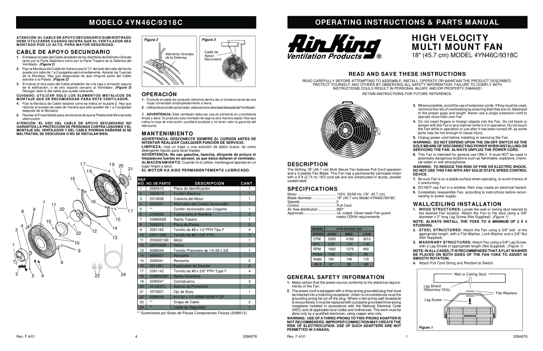
1.Entrelazar el cabo del Cable alrededor de los Alambres de Diámetro Grande tanto por la Parte Delantera como por la Parte Trasera de la Defensa del Ventilador. (Figura 2)
2.Fijar la Mordaza del Cable de manera que la "U" del lado del cabo del bucle quede con cabo de 1 a 2 pulgadas aproximadamente. Apretar las Tuercas de la Mordaza. Hay que asegurarse de que ninguna parte del Cable estorbe a la Paleta. (Figura 2)
3.Enroscar el otra cabo del Cable alrededor de una viga o armazón segura de la edificación, o de otro soporte cercano al Ventilador. (Figura 3) Recoger todo lo del cable que quede sobrando.
CUIDADO: UTILIZAR SÓLO LOS ELEMENTOS METÁLICOS DE MONTAJE QUE SE RECOMIENDAN PARA ESTE VENTILADOR.
Figura 2 |
| Figura 3 |
| Alambres Grandes | Cable de |
| Apoyo | |
| de la Defensa | |
| Secundario | |
|
|
OPERACIÓN
1. Enchufe el cable de conexión eléctrica dentro de un tomacorriente de tres |
HIGH VELOCITY
MULTI MOUNT FAN
18" (45.7 cm) MODEL 4YN46C/9318C
READ AND SAVE THESE INSTRUCTIONS
READ CAREFULLY BEFORE ATTEMPTING TO ASSEMBLE, INSTALL, OPERATE OR MAINTAIN THE PRODUCT DESCRIBED.
PROTECT YOURSELF AND OTHERS BY OBSERVING ALL SAFETY INFORMATION. FAILURE TO COMPLY WITH
INSTRUCTIONS COULD RESULT IN PERSONAL INJURY AND/OR PROPERTY DAMAGE!
RETAIN INSTRUCTIONS FOR FUTURE REFERENCE.
4.Fijar la Mordaza de Cable restante como se indica en la parte 2. Hay que recortar el exceso de cabo de manera que sólo queden de 1 a 2 pulgadas después de la Mordaza
5.Revisar el Ensamblado para cerciorarse de que la Paleta esté libre de toda obstrucción.
ATENCIÓN: EL USO DEL CABLE DE APOYO SECUNDARIO NO GARANTIZA LA PROTECCIÓN DE PERSONAS CONTRA LESIONES Y EL MONTAJE DEL VENTILADOR Y DEL CABLE PODRÍAN DAÑARSE SI SE MALTRATAN, SE DESCUIDAN O NO SE INSTALAN BIEN.
1 71 9 20
1 8 | 21 |
|
15
|
|
| 7 | 11 | 16 |
|
|
|
|
|
|
| |
| 8 | 9 |
| 22 |
| 1 7 |
|
|
|
|
| ||
|
|
|
| 10 |
| 15 |
| 4 |
|
|
|
| |
3 |
|
|
|
| 14 | |
|
|
|
| 12 | ||
|
|
| 22 |
| ||
|
|
|
|
| ||
|
|
|
|
| 13 | |
|
|
|
|
|
| |
1 |
|
|
| 10 |
|
|
|
|
|
|
|
| |
|
|
|
| 9 |
|
|
|
|
|
| 8 |
|
|
2 |
| 5 | 6 |
| 23 | 24 |
hojas conectado ampropiadamente a tierra. |
2. Utilizando el cordón accionador, seleccione la velocidad deseada del Ventilador. |
3. ADVERTENCIA: Este ventilador debe ser usa do solmente en unambiente |
limpio y seco. Si producto esta montado de alguna otra manera espec´ifica que |
indica la hoja de instrucción, purdiera anularse y no tener valor la garantia del |
fabricante. |
MANTENIMIENTO
ADVERTENCIA: DESCONECTE SIEMPRE EL CORDÓN ANTES DE INTENTAR REALIZAR CUALQUIER FUNCIÓN DE SERVICIO.
LIMPIEZA: Use un trapo y una solución de jabón suave, tal como detergente líquido para lavar trastes.
ADVERTENCIA: No use gasolina, bencina, diluyente de pintura ni limpiadores fuertes en aerosol, ya que éstos dañarán el ventilador.
ALMACENAMIENTO: Cuando no lo utilice, mantenga el aparato en un
lugar limpio y seco.
EL MOTOR HA SIDO PERMANENTEMENTE LUBRICADO.
REF |
| DESCRIPCIÓN | CANT. | |
| ||||
NO. | NO. DE PARTE | |||
|
|
|
| |
1 | 2065510 | Placa de Identificación | 1 | |
2 | 2050015 | Cordón Eléctrico | 1 | |
3 | 2010636 | Cubierta del Motor | 1 | |
|
|
|
| |
4 | 2055001 | Interruptor del Cordón Accionador | 1 | |
5 | ** | Cordón Accionador con Colgante | 1 | |
|
|
|
| |
6 | 2090552 | Tuerca para el Alambre | 2 | |
7 | 5096056B | Rejilla Trasera | 1 | |
|
|
|
| |
8 | 5060015 | Placa de Pivote | 2 | |
9 | 2091162 | Tornillo de #8 x 1/2 PPH Tipo F | 4 | |
|
|
|
| |
10 | 2091126B | Tornillo de #6 x 5/8" PTH | 3 | |
11 | 2030021SB | Motor | 1 | |
|
|
|
| |
12 | 5081050B | Hélice | 1 | |
13 | 5090044 | Tornillo Prisionero de | 1 | |
14 | 5060027 | Horqueta | 1 | |
15 | 5090041 | Remache | 2 | |
|
|
|
| |
16 | 2011601 | Espaciador de Caucho | 2 | |
17 | 2091143 | Tornillo de #8 x 3/8" PPH Type F | 4 | |
|
|
|
| |
18 | 5096052BK | Rejilla Delantera | 1 | |
19 | 2090547 | Contratuerca | 3 | |
|
|
|
| |
20 | 2010237L | Adorno de Protección | 1 | |
21 | 2070027 | Ojo de Buey | 1 | |
|
|
|
| |
22 | 5090045 |
| ||
23 | ** | Grapa de Cable | 2 | |
|
|
|
| |
24 | ** | Cable de Seguridad | 1 |
** Suministros por Bolso de Piezas Componentes Físicas (2098012)
DESCRIPTION
The AirKing 18" (45.7 cm) Multi Mount Fan features Pull Cord operation and a
SPECIFICATIONS
Motor |
| 120V, 50/60 Hz (18", 45.7 cm) | |||||
Blade diameter |
| 18" (45.7 cm) Model 4YN46C/9318C | |||||
Speeds | 3 |
|
|
|
| ||
Control | Pull Cord |
|
| ||||
Air flow distribution | 360° |
|
|
| |||
Approvals |
| UL Listed. Close mesh Fan guard | |||||
|
| meets OSHA requirements. | |||||
|
|
|
|
|
|
| |
| MODEL | 4YN46C/9318C |
|
| |||
| SPEED | HIGH |
| MED |
| LOW |
|
| CFM | 5350 |
| 4180 |
| 3010 |
|
|
|
|
|
|
|
|
|
| M3/s | 2.52 |
| 1.97 |
| 1.42 |
|
| RPM | 1600 |
| 1275 |
| 950 |
|
|
|
|
|
|
|
|
|
| Amps | 1.65 |
| 1.27 |
| .95 |
|
| Watts | 194 |
| 148 |
| 110 |
|
|
|
|
|
|
|
|
|
| dB A | 67 |
| 58 |
| 49 |
|
GENERAL SAFETY INFORMATION
1.Make certain that the power source conforms to the electrical require- ments of the Fan.
2.The power cord is equipped with a
WARNING: USE OF A
3.Where possible, avoid the use of extension cords. If they must be used, minimize the risk of overheating by ensuring that they are UL listed and of the proper gage and length. Never use a single extension cord to operate more than one Fan.
4.Do not insert fingers or foreign objects into the Fan. Do not block or tamper with the Fan in any manner while it is in operation. Do not touch the Fan while in operation or just after it has been turned off, as some parts may be hot enough to cause injury.
5.Unplug power cord before installing or servicing the Fan.
WARNING: DO NOT DEPEND UPON THE
6.This Fan is intended for general use ONLY. It must NOT be used in potentially dangerous locations such as flammable, explosive, chemi-
WARNING: TO REDUCE THE RISK OF FIRE OR ELECTRIC SHOCK, DO NOT USE THIS FAN WITH ANY SOLID STATE SPEED CONTROL DEVICE.
7.Be sure Fan is on a stable surface when operating, to avoid chance of it overturning.
8.DO NOT use Fan in a window. Rain may create an electrical hazard.
9.Completely reassemble Fan, according to instructions before recon- necting to power supply.
WALL/CEILING INSTALLATION
1.WOOD STRUCTURES: Locate the wall or ceiling stud nearest to the desired Fan location. Attach the Fan to the stud using a 3/8" diameter x 2" long Lag Screw (Not Supplied). (Figure 1)
NOTE: ALWAYS INSTALL THE YOKE TO A MINIMUM OF 2 X 4 STUDDING.
2.STEEL STRUCTURES: Attach the Fan using a 3/8" bolt of the appropriate length, with a Flat Washer, Lock Washer and a 3/8" Nut (Not Supplied).
3.MASONARY STRUCTURES: Attach Fan using a 3/8" Lag Screw, with a Lag Shield of appropriate length (Not Supplied). (Figure 1)
NOTE: IN ALL CASES, IT IS RECOMMENDED THAT A FLAT WASHER BE PLACED ON BOTH SIDES OF THE FAN YOKE TO ASSIST IN SMOOTH ROTATION.
4.Attach Pull Cord String and Pendant to Switch.
![]() Wall or Ceiling Stud
Wall or Ceiling Stud ![]()
Lag Shield
(Masonary Only)
Flat Washers
Lag Screw ![]()
![]()
Figure 1
Rev. F 4/01 | 4 | 2084576 |
Rev. F 4/01 | 1 | 2084576 |