OPERATING INSTRUCTIONS & PARTS MANUAL
HIGH VELOCITY
I-BEAM MOUNT FAN
18" (45.7 cm) MODEL 9618
READ AND SAVE THESE INSTRUCTIONS
READ CAREFULLY BEFORE ATTEMPTING TO ASSEMBLE, INSTALL, OPERATE OR MAINTAIN THE PRODUCT DESCRIBED.
PROTECT YOURSELF AND OTHERS BY OBSERVING ALL SAFETY INFORMATION. FAILURE TO COMPLY WITH
INSTRUCTIONS COULD RESULT IN PERSONAL INJURY AND/OR PROPERTY DAMAGE!
RETAIN INSTRUCTIONS FOR FUTURE REFERENCE.
DESCRIPTION
The AirKing 18" (45.7 cm)
WARNING: TO REDUCE THE RISK OF FIRE OR ELECTRIC SHOCK, DO NOT USE THIS FAN WITH ANY SOLID STATE SPEED CONTROL DEVICE.
CAUTION: BECAUSE OF SIZE AND WEIGHT OF THIS FAN, MAKE SURE ALL PARTS ARE COMPLETELY ASSEMBLED ACCORDING TO INSTRUCTIONS. FAILURE TO DO SO COULD RESULT IN FAN COM- ING APART DURING OPERATION AND/OR PERSONAL INJURY.
SPECIFICATIONS
Motor | 120 V, 50/60 Hz |
|
| ||||
Blade diameter | 18" (45.7 cm) Model 9618 | ||||||
Speeds | 3 |
|
|
|
|
| |
Control | Pull Cord |
|
| ||||
Air flow distribution | 360° |
|
|
|
| ||
Approvals | UL Listed. Close mesh Fan guard | ||||||
|
| meets OSHA requirements. | |||||
|
|
|
|
|
|
|
|
| MODEL |
|
| 9618 |
|
|
|
| SPEED | HIGH |
| MED |
| LOW |
|
| CFM | 5350 |
| 4180 |
| 3010 |
|
|
|
|
|
|
|
|
|
| M3/s | 2.52 |
| 1.97 |
| 1.42 |
|
| RPM | 1600 |
| 1275 |
| 950 |
|
|
|
|
|
|
|
|
|
| Amps | 1.65 |
| 1.27 |
| .95 |
|
| Watts | 194 |
| 148 |
| 110 |
|
|
|
|
|
|
|
|
|
| dB A | 67 |
| 58 |
| 49 |
|
GENERAL SAFETY INFORMATION
1.Make certain that the power source conforms to the electrical require- ments of the Fan.
2.The power cord is equipped with a
WARNING: USE OF A
3.Where possible, avoid the use of extension cords. If they must be used, minimize the risk of overheating by ensuring that they are UL listed and of the proper gage and length. Never use a single extension cord to operate more than one fan.
4.Do not insert fingers or foreign objects into the fan. Do not block or tamper with the fan in any manner while it is in operation. Do not touch the fan while in operation or just after it has been turned off, as some parts may be hot enough to cause injury.
5.Unplug power cord before installing or servicing the fan.
WARNING: DO NOT DEPEND UPON THE
6.This fan is intended for general use ONLY. It must NOT be used in potentially dangerous locations such as flammable, explosive, chemi-
New 6/01
7.Be sure Fan is mounted to a stable surface when operating.
8.DO NOT mount Fan near windows or bay doors. Rain may create an electrical hazard.
9.Completely reassemble Fan, according to instructions before recon- necting to power supply.
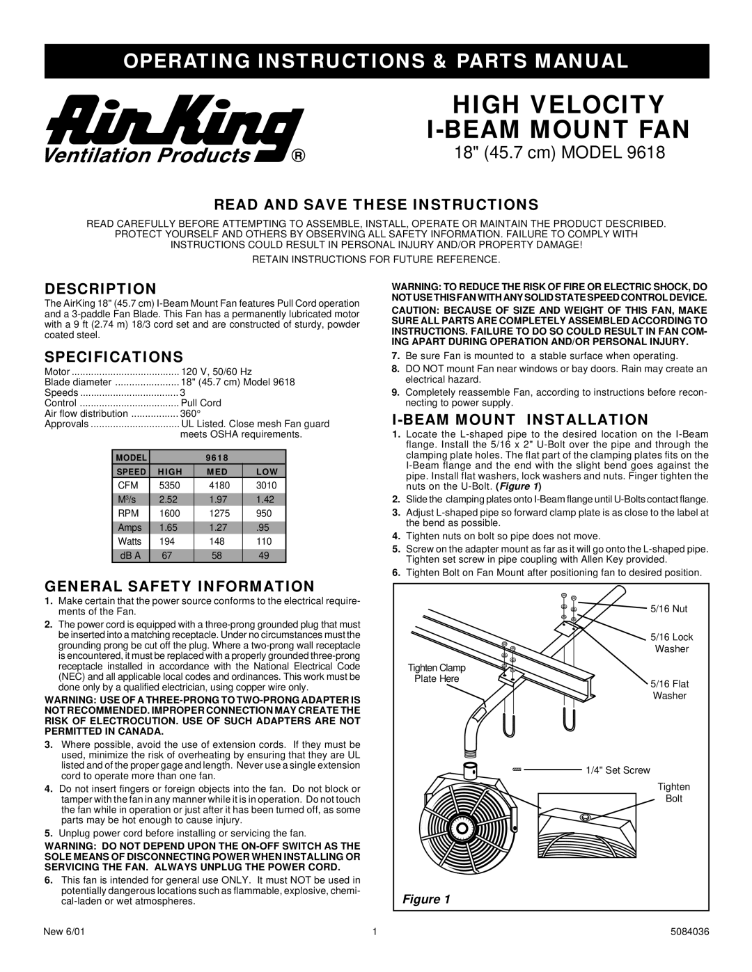
I-BEAM MOUNT INSTALLATION
1.Locate the
2.Slide the clamping plates onto
3.Adjust
4.Tighten nuts on bolt so pipe does not move.
5.Screw on the adapter mount as far as it will go onto the
6.Tighten Bolt on Fan Mount after positioning fan to desired position.
|
| 5/16 Nut |
|
| 5/16 Lock |
|
| Washer |
| Tighten Clamp |
|
| Plate Here | 5/16 Flat |
|
| |
|
| Washer |
|
| 1/4" Set Screw |
|
| Tighten |
|
| Bolt |
| Figure 1 |
|
1 |
| 5084036 |