ASW324 specifications
The Airlink101 ASW324 is a robust and versatile wireless router that caters to both home users and small businesses looking for a reliable networking solution. With its advanced features and commendable performance, it stands out as a valuable asset in today’s digital landscape.One of the main features of the ASW324 is its dual-band capability, which operates on 2.4 GHz and 5 GHz frequencies. This dual-band functionality significantly enhances connectivity options, allowing users to allocate bandwidth based on their specific needs. The 2.4 GHz band, known for its wider coverage, is ideal for general browsing and streaming, while the 5 GHz band provides faster speeds for high-bandwidth activities such as online gaming and video conferencing.
The ASW324 is equipped with a powerful 802.11ac wireless standard, enabling high-speed wireless transmission with data rates of up to 1200 Mbps. This ensures that multiple devices can connect simultaneously without any noticeable dip in performance. Coupled with advanced MIMO (Multiple Input Multiple Output) technology, the router effectively manages multiple user connections, enhancing throughput and minimizing interference.
Security is another key characteristic of the Airlink101 ASW324. It comes with robust encryption protocols, including WPA/WPA2, ensuring that users' data remains protected against potential threats. Additionally, the router features a built-in firewall, providing an extra layer of security from external attacks while allowing users to customize access controls.
Another noteworthy attribute is its easy setup and user-friendly interface. The ASW324 comes with an intuitive web-based management portal, allowing even novice users to configure their networks with ease. The included Quick Setup Wizard simplifies the installation process, enabling users to connect and start using the internet within minutes.
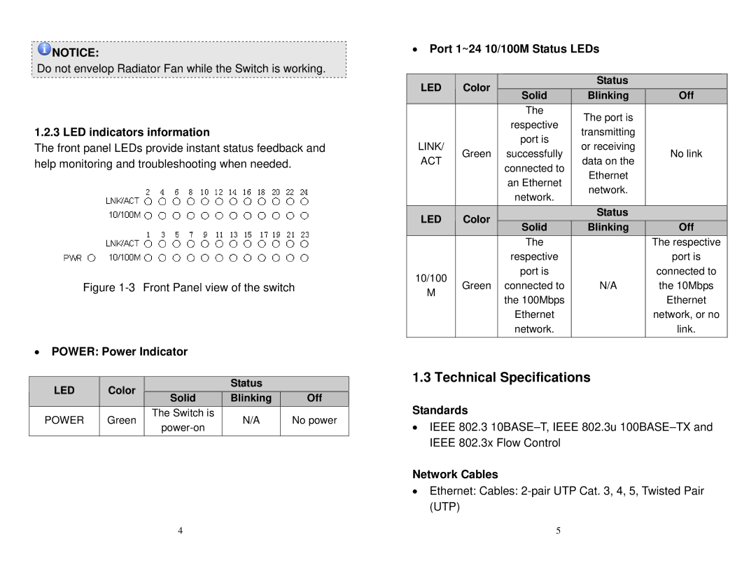
Moreover, the ASW324 includes multiple gigabit LAN ports, providing high-speed wired connections for devices that require stable and fast internet access, such as gaming consoles, PCs, and streaming devices. This blend of wired and wireless connectivity options ensures that all user requirements are met.
In conclusion, the Airlink101 ASW324 combines advanced features, solid technologies, and reliable performance into a single package. Its dual-band wireless capability, high-speed data rates, strong security configurations, and easy management make it an appealing choice for anyone seeking to enhance their home or office networking experience.

