Pin No. |
|
| Pin Name | I/O |
| Description |
|
|
|
|
|
|
|
43 |
|
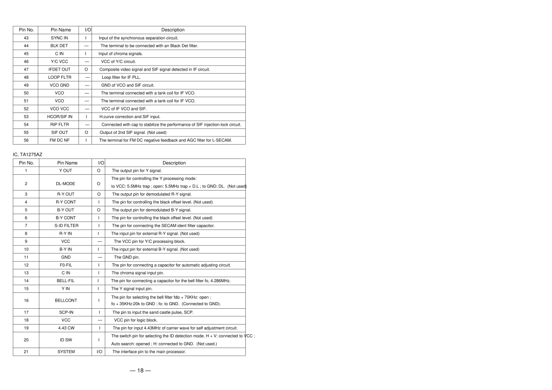
| SYNC IN | I | Input of the synchronous separation circuit. | |
|
|
|
|
|
|
|
44 |
|
| BLK DET | – | The terminal to be connected with an Black Det filter. | |
|
|
|
|
|
|
|
45 |
|
| C IN | I | Input of chroma signals. | |
|
|
|
|
|
|
|
46 |
|
| Y/C VCC | – | VCC of Y/C circuit. | |
|
|
|
|
|
|
|
47 |
|
| IFDET OUT | O | Composite video signal and SIF signal detected in IF circuit. | |
|
|
|
|
|
|
|
48 |
|
| LOOP FLTR | – | Loop filter for IF PLL. | |
|
|
|
|
|
|
|
49 |
|
| VCO GND | – | GND of VCO and SIF circuit. | |
|
|
|
|
|
|
|
50 |
|
| VCO | – | The terminal connected with a tank coil for IF VCO. | |
|
|
|
|
|
|
|
51 |
|
| VCO | – | The terminal connected with a tank coil for IF VCO. | |
|
|
|
|
|
|
|
52 |
|
| VCO VCC | – | VCC of IF VCO and SIF. | |
|
|
|
|
|
|
|
53 |
|
| HCOR/SIF IN | I | H.curve correction and SIF input. | |
|
|
|
|
|
|
|
54 |
|
| RIP FLTR | – | Connected with cap to stabilize the performance of SIF | |
|
|
|
|
|
|
|
55 |
|
| SIF OUT | O | Output of 2nd SIF signal. (Not used) | |
|
|
|
|
|
|
|
56 |
|
| FM DC NF | I | The terminal for FM DC negative feedback and AGC filter for | |
|
|
|
|
|
|
|
IC, TA1275AZ |
|
|
|
| ||
|
|
|
|
|
| |
Pin No. |
| Pin Name |
| I/O | Description | |
|
|
|
|
|
|
|
1 |
|
| Y OUT |
| O | The output pin for Y signal. |
|
|
|
|
|
|
|
|
|
|
|
|
| The pin for controlling the Y processing mode: |
2 |
|
|
| O | to VCC: 5.5MHz trap ; open: 5.5MHz trap + D.L ; to GND: DL. (Not used) | |
|
|
|
|
|
| |
|
|
|
|
|
|
|
3 |
|
|
| O | The output pin for demodulated | |
|
|
|
|
|
|
|
4 |
|
|
| I | The pin for controlling the black offset level. (Not used) | |
|
|
|
|
|
|
|
5 |
|
|
| O | The output pin for demodulated | |
|
|
|
|
|
|
|
6 |
|
|
| I | The pin for controlling the black offset level. (Not used) | |
|
|
|
|
|
|
|
7 |
|
|
|
| I | The pin for connecting the SECAM ident filter capacitor. |
|
|
|
|
|
|
|
8 |
|
|
| I | The input pin for external | |
|
|
|
|
|
|
|
9 |
|
| VCC |
| – | The VCC pin for Y/C processing block. |
|
|
|
|
|
|
|
10 |
|
|
| I | The input pin for external | |
|
|
|
|
|
|
|
11 |
|
| GND |
| – | The GND pin. |
|
|
|
|
|
|
|
12 |
|
|
| I | The pin for connecting a capacitor for automatic adjusting circuit. | |
|
|
|
|
|
|
|
13 |
|
| C IN |
| I | The chroma signal input pin. |
|
|
|
|
|
|
|
14 |
|
|
| I | The pin for connecting a capacitor for the bell filter fo, 4.286MHz. | |
|
|
|
|
|
|
|
15 |
|
| Y IN |
| I | The Y signal input pin. |
|
|
|
|
|
|
|
16 |
|
| BELLCONT |
| I | The pin for selecting the bell filter fo. fo + 70KHz: open ; |
|
|
| fo + 35KHz:20k to GND ; fo: to GND. (Connected to GND). | |||
|
|
|
|
|
| |
|
|
|
|
|
|
|
17 |
|
|
| I | The pin to input the sand castle pulse, SCP. | |
|
|
|
|
|
|
|
18 |
|
| VCC |
| – | VCC pin for logic block. |
|
|
|
|
|
|
|
19 |
|
| 4.43 CW |
| I | The pin for input 4.43MHz of carrier wave for self adjustment circuit. |
|
|
|
|
|
|
|
20 |
|
| ID SW |
| I | The switch pin for selecting the ID detection mode. H + V: connected to VCC ; |
|
|
| Auto search: opened ; H: connected to GND. (Not used.) | |||
|
|
|
|
|
| |
|
|
|
|
|
|
|
21 |
|
| SYSTEM |
| I/O | The interface pin to the main processor. |
|
|
|
|
|
|
|
– 18 –