HT 81, PT 81, PR 81 specifications
AKG Acoustics has long been recognized as a leader in the field of professional audio equipment, and their HT 81, PR 81, and PT 81 microphones exemplify the brand's commitment to quality, innovation, and user-centric design. These microphones are particularly suited for applications in live sound, broadcast, and studio recording, making them versatile tools for audio professionals.The AKG HT 81 handheld transmitter microphone is designed for wireless performance. It features a dynamic capsule that delivers a clear and natural sound, a significant advantage for vocal performances. The microphone is engineered to minimize handling noise and feedback, ensuring that the audio remains pristine even in challenging environments. Its robust build quality can withstand the rigors of touring and live shows, making it a reliable choice for entertainers on stage.
Complementing the HT 81, the PR 81 is a professional receiver that supports a wide frequency range, allowing for clear audio transmission without interference. This receiver is equipped with advanced diversity reception technology, which helps mitigate dropouts and ensures consistent audio quality, even in crowded RF environments. The PR 81 offers a range of connectivity options, enabling easy integration into existing audio systems, whether in venues or broadcasting setups.
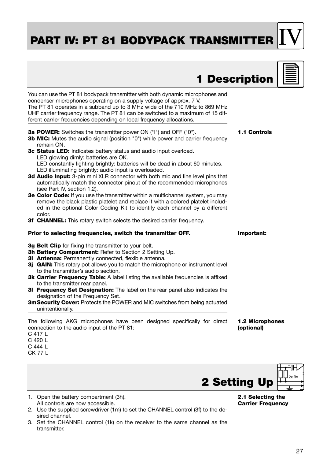
The PT 81 bodypack transmitter is another integral component of this series, designed for use with lavalier or headset microphones. It features a lightweight and ergonomic design, ensuring comfort for performers during extended use. The PT 81 is equipped with a high-quality analog audio input, allowing for seamless connection to a variety of microphones. Its long battery life is a significant advantage, providing reliable operation for long events or sessions.
All three devices utilize AKG’s advanced wireless technology, which incorporates digital signal processing for enhanced audio quality and reduced noise interference. The system also offers multiple channels, allowing for the simultaneous use of multiple microphones without conflict. With quick and easy setup, users can spend more time focusing on performance rather than troubleshooting audio issues.
Overall, the AKG HT 81, PR 81, and PT 81 represent a powerful trio of wireless audio solutions. Their combination of durability, sound quality, and user-friendly features makes them an excellent choice for any professional looking to elevate their audio experience. Whether for stage, studio, or broadcast applications, these microphones stand out as reliable tools that deliver outstanding performance.

