Installations
multiple loudspeakers or systems to any amplifier, care should be taken that the actual load impedance does not drop below the amplifierÕs rated output load. Alesis amplifiers will not be damaged by excessively low output load impedances, but they will not be able to provide full output power and their protection circuits may automatically cut off their outputs until the low load condition is removed.
Gauge | Diameter | DC Resist./ | Cable Length Resulting in a 1 dB Power Loss | |||
(AWG) | (Solid) | 30 m (100Õ) | 4 Ω Load Impedance | 8 Ω Load Impedance | ||
6 | 4.12 mm | 0.08 Ω | 366 m | 1200Õ | 740 m | 2400Õ |
8 | 3.26 mm | 0.13 Ω | 244 m | 800Õ | 488 m | 1600Õ |
10 | 2.59 mm | 0.20 Ω | 145 m | 475Õ | 290 m | 950Õ |
12 | 2.05 mm | 0.32 Ω | 91 m | 300Õ | 182 m | 600Õ |
14 | 1.63 mm | 0.52 Ω | 58 m | 190Õ | 116 m | 380Õ |
16 | 1.29 mm | 0.82 Ω | 37 m | 120Õ | 74 m | 240Õ |
18 | 1.02 mm | 1.32 Ω | 23 m | 75Õ | 46 m | 150Õ |
20 | 0.81 mm | 2.08 Ω | 15 m | 50Õ | 30 m | 100Õ |
22 | 0.64 mm | 3.30 Ω | 9 m | 30Õ | 18 m | 60Õ |
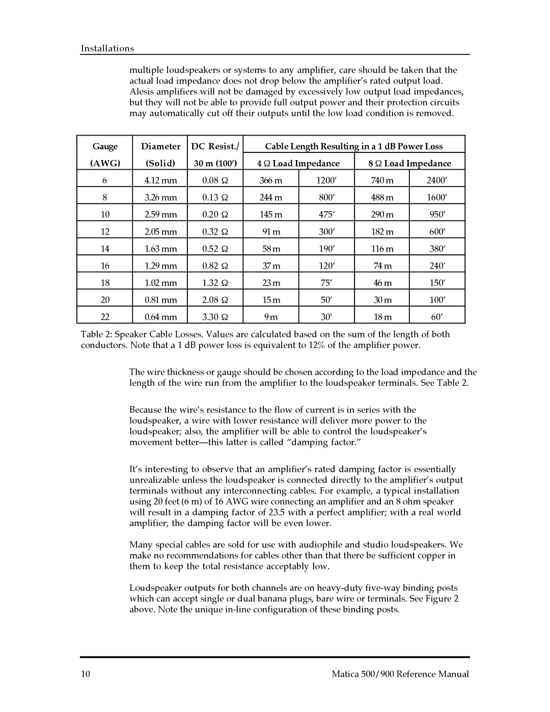
Table 2: Speaker Cable Losses. Values are calculated based on the sum of the length of both conductors. Note that a 1 dB power loss is equivalent to 12% of the amplifier power.
The wire thickness or gauge should be chosen according to the load impedance and the length of the wire run from the amplifier to the loudspeaker terminals. See Table 2.
Because the wireÕs resistance to the flow of current is in series with the loudspeaker, a wire with lower resistance will deliver more power to the loudspeaker; also, the amplifier will be able to control the loudspeakerÕs movement betterÑthis latter is called Òdamping factor.Ó
ItÕs interesting to observe that an amplifierÕs rated damping factor is essentially unrealizable unless the loudspeaker is connected directly to the amplifierÕs output terminals without any interconnecting cables. For example, a typical installation using 20 feet (6 m) of 16 AWG wire connecting an amplifier and an 8 ohm speaker will result in a damping factor of 23.5 with a perfect amplifier; with a real world amplifier, the damping factor will be even lower.
Many special cables are sold for use with audiophile and studio loudspeakers. We make no recommendations for cables other than that there be sufficient copper in them to keep the total resistance acceptably low.
Loudspeaker outputs for both channels are on
10 | Matica 500/900 Reference Manual |
