4AC18LT specifications
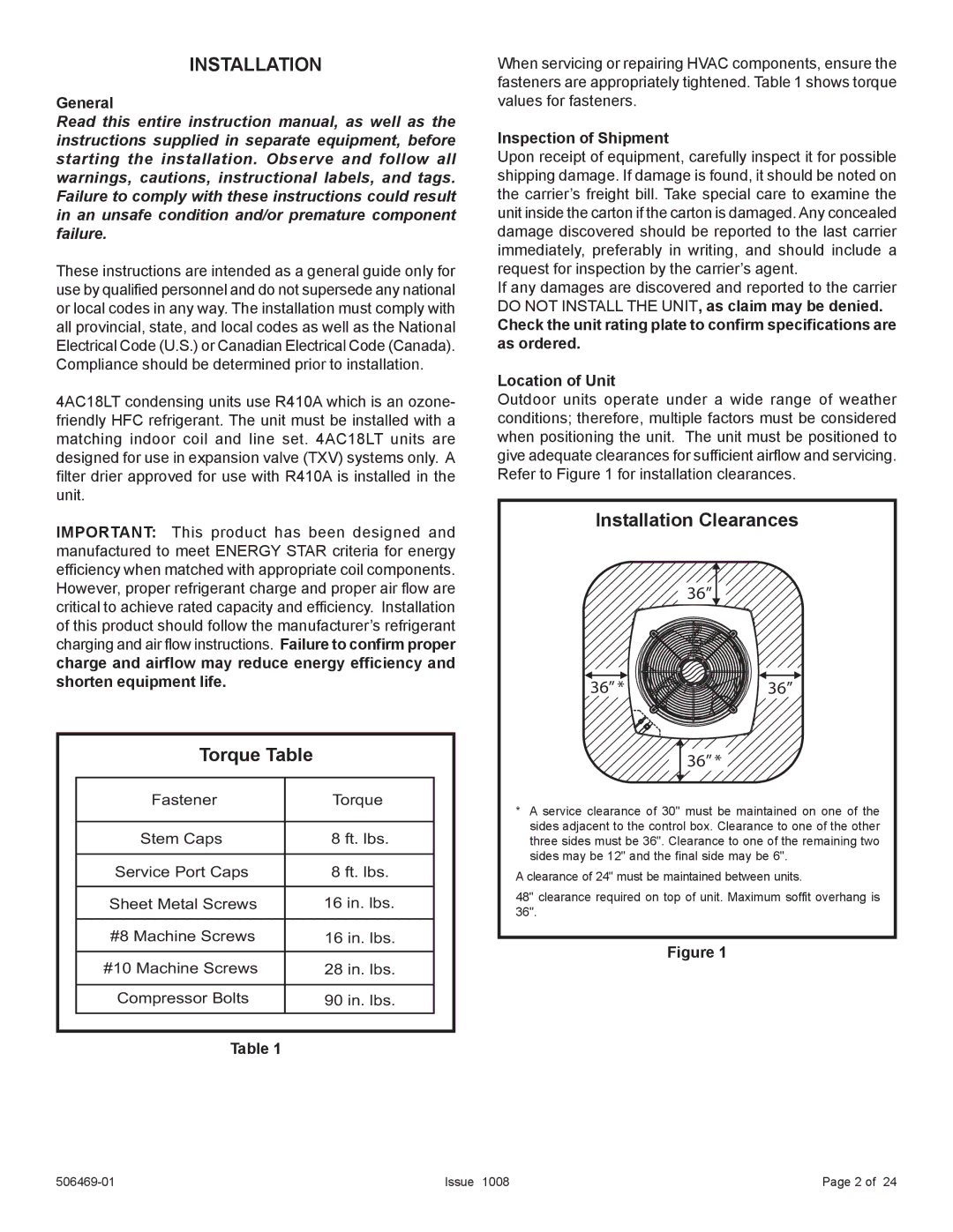
Allied Air Enterprises has made significant strides in the HVAC industry with the introduction of its 4AC18LT air conditioner. This model is part of a premium line of products that emphasizes efficiency, reliability, and advanced cooling technology. The 4AC18LT is specifically designed to meet the diverse needs of both residential and light commercial applications, making it a versatile choice for many consumers.One of the standout features of the 4AC18LT is its impressive Seasonal Energy Efficiency Ratio (SEER) rating. With a SEER rating of up to 18, this unit is engineered to provide excellent energy efficiency, significantly reducing electricity consumption while delivering consistent cooling performance. As energy costs continue to rise, homeowners and businesses can benefit greatly from this efficiency, leading to lower monthly utility bills and a reduced carbon footprint.
The 4AC18LT employs advanced R-410A refrigerant, which is known for its environmentally friendly properties. Unlike older refrigerants that contribute to ozone depletion, R-410A is more stable and offers better heat transfer capabilities, which enhances the overall performance of the unit. This focus on eco-friendliness aligns with contemporary environmental standards and regulations, ensuring that users are making a responsible choice for their cooling needs.
In terms of design, the 4AC18LT features a robust and compact frame that is built to withstand the rigors of outdoor installation. The unit's durability is further enhanced by its corrosion-resistant finish, which protects the coil and cabinet from harsh weather conditions, extending the life span of the system.
Noise reduction technology is another highlight of the 4AC18LT. This model is designed with a quieter operation in mind, utilizing a sound blanket and insulated compressor compartment. These features work together to minimize noise levels, allowing users to enjoy a comfortable indoor environment without disruptive sound.
The 4AC18LT also supports advanced controls and compatibility with smart thermostats, providing users with greater flexibility and convenience. Homeowners can take advantage of programmable features, enabling them to optimize cooling schedules for energy savings and increased comfort.
Overall, Allied Air Enterprises’ 4AC18LT air conditioner combines efficiency, environmental responsibility, durability, and user-friendly features, making it an excellent choice for those in need of reliable cooling solutions. Whether installed in a residential or light commercial setting, the 4AC18LT promises to deliver exceptional performance and peace of mind.

