
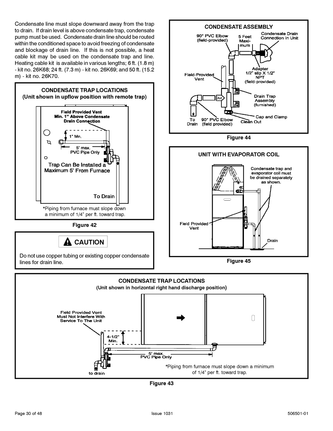
92G1UH, 95G1UH, A95UH, A93UH specifications
Allied Air Enterprises is renowned for producing high-quality HVAC systems, and its models A93UH, 92G1UH, A95UH, and 95G1UH are no exception. These units exemplify cutting-edge technology, efficiency, and reliability, making them popular choices for residential and commercial applications.The A93UH model is a high-efficiency gas furnace designed with advanced features that maximize performance while maintaining low operating costs. It boasts a 93% Annual Fuel Utilization Efficiency (AFUE) rating, which ensures that a significant portion of the fuel consumed translates into heat. The A93UH incorporates variable-speed blower technology, allowing for precise airflow adjustments that enhance comfort and energy savings.
Similarly, the 92G1UH is built to provide exceptional heating capabilities. With a robust construction and innovative design, this model also achieves a 92% AFUE rating. It features a durable heat exchanger and a reliable ignition system that ensures consistent performance. The 92G1UH is engineered for quiet operation, minimizing noise levels and contributing to a more comfortable indoor environment.
Moving on to the A95UH, this unit represents the pinnacle of efficiency with its impressive 95% AFUE rating. This model not only emphasizes energy savings but also focuses on long-term durability. Equipped with a two-stage gas valve, the A95UH allows for flexible heating based on demand, which translates into enhanced comfort and efficiency. Additionally, the integrated SmartComfort technology provides homeowners with user-friendly control options.
The 95G1UH model shares many of the same advanced features as the A95UH but is tailored for different installation scenarios. With a comparable efficiency rating, the 95G1UH emphasizes ease of maintenance and installation. Its compact design and lightweight construction make it an ideal choice for various settings where space is limited.
All four models incorporate the latest in comfort control technology, allowing for seamless connectivity and programmability. Homeowners can utilize smart thermostats to optimize their heating schedules, further enhancing energy savings. The featured robust warranty and service support from Allied Air Enterprises provide peace of mind, ensuring that these units will deliver reliable performance for years to come.
Overall, the A93UH, 92G1UH, A95UH, and 95G1UH models stand out in the HVAC market due to their efficiency, innovative features, and durability. These units cater to a variety of heating needs while keeping operational costs low, making them wise investments for any property owner.