AT-MCF2000AC specifications
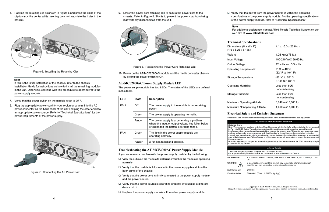
The Allied Telesis AT-MCF2000AC is a robust and versatile managed gigabit fiber switch designed for use in enterprise networks, data centers, and telecommunications applications. It is engineered to provide high-performance connectivity, ensuring that organizations can effectively manage their network traffic and maintain peak operational efficiency.One of the key features of the AT-MCF2000AC is its support for both copper and fiber optic connections. It provides a variety of port options, including 10/100/1000Base-T and SFP slot configurations, allowing for greater flexibility in connecting various devices across the network. This adaptability makes it an ideal choice for businesses looking to expand their infrastructure without being constrained by fixed connection types.
The switch is equipped with advanced Layer 2 and Layer 3 switching capabilities, enabling effective routing and management of smart traffic. It supports VLAN tagging for network segmentation, security, and improved performance, allowing administrators to optimize bandwidth usage and enhance overall network security. The AT-MCF2000AC includes multiple Quality of Service (QoS) policies, which prioritize essential data and applications, ensuring optimal performance for critical business operations.
A highlight of the AT-MCF2000AC is its energy-efficient design. It complies with Energy Star standards, promoting environmentally friendly practices in data centers and IT operations. This energy efficiency not only reduces operational costs but also contributes to a greener technology footprint.
Additionally, the AT-MCF2000AC is packed with robust security features. It supports various authentication methods, including 802.1X, ensuring that only authorized devices can access the network. The switch also offers port security functions that protect against unauthorized access by limiting connection attempts and tracking MAC addresses.
Management and monitoring are straightforward with the AT-MCF2000AC. It features a user-friendly web interface, SNMP support, and CLI options for network administrators to easily configure and oversee the performance of the switch. Event logging and diagnostic tools aid in troubleshooting potential issues, ensuring minimal downtime.
The AT-MCF2000AC is compatible with Allied Telesis' comprehensive network management software, allowing for centralized management of switches and other devices within the network. It serves as a valuable component in building scalable, high-performance, and secure networks suited for modern enterprise needs. Through its combination of advanced features, reliable performance, and efficient design, the Allied Telesis AT-MCF2000AC enhances network infrastructure while supporting the growing demands of businesses today.

