2. On the back of the |
corresponds to the slot where you are going to install the power supply and |
verify that the On/Off button is in the Off (out) position. From left to right on |
the back, the power supplies are identified as B2, B1, A2, A1. (An AT- |
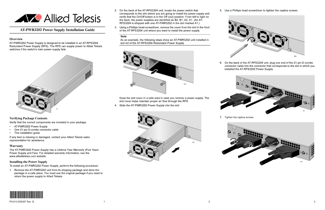
5. Use a Phillips head screwdriver to tighten the captive screws.
AT-PWR3202 Power Supply Installation Guide
Overview
RPS3204 is shipped with one |
3. Using a Phillips head screwdriver, remove the cover from the slot in the front |
of the |
Note
As an example, the following steps show an
STATUS
STATUS
| AT- |
|
| |
| 12V | PWR3202 | ||
|
| DC | ,16.6A |
|
POWER |
|
| MAX | |
|
|
| ||
|
|
|
| |
FAULT |
|
|
|
|
STATUS
| AT- |
|
|
|
| PW | R3202 | ||
| 12VDC |
| ||
POWER |
| ,16.6A | MAX | |
|
|
|
| |
FAULT |
|
|
|
|
895
R3202 | |||
12VDC |
| ||
POWER | ,16.6A | MAX | |
|
|
| |
F |
|
|
|
AULT |
|
|
|
6.On the back of the
STATUS
| R3202 | |||
| 12VDC |
| ||
POWER |
| ,16.6A | MAX | |
|
|
|
| |
FAULT |
|
|
|
|
892
Verifying Package Contents
Verify that the correct components are included in your package:
893
Keep the slot cover in a safe area in case you remove a power supply. The slot cover helps maintain proper air flow through the RPS.
4. Slide the
STATUS
R |
| ||
12VDC |
|
| |
|
| 3202 | |
POWER | ,16.6A | MAX | |
|
|
| |
FAULT |
|
|
|
![]() ON
ON
![]() OFF
OFF
A2
OU |
|
TPUT | A2 |
12VDC |
AC |
|
|
|
INPUT | A2/A1 | ||
100 | - 240 |
| |
|
| VAC ~ | |
RPS |
|
O |
|
UTPUT | A1 |
12VDC |
7.Tighten the captive screws.
A1 | ON |
| OFF |
198 |
|
•
•One
•This installation guide
If any item is missing or damaged, contact your Allied Telesis sales representative for assistance.
Warranty
The
Installing the Power Supply
To install an
1.Remove the
*613-000397 Rev B*
894
STATUS
| R3202 | |||
| 12VDC |
| ||
POWER |
| ,16.6A | MAX | |
|
|
|
| |
FAULT |
|
|
|
|
![]() ON
ON ![]() OFF
OFF
![]() A2
A2
RPS | OUTPUT |
|
| A2 | |
| 12VDC |
AC |
|
|
|
|
INPUT | A2/A1 | |||
100 | - | 240 |
| |
| VAC ~ | |||
|
|
| ||
RPS | OUTPUT |
|
| A1 | |
| 12VDC |
A1 | ON |
| OFF |
199 |
|
PN | 1 | 2 | 3 |