13. Verify that the On/Off switches for the power supplies marked A1 and A2 are | 20. Plug one end of the |
in the Off (out) position. | labeled “RPS INPUT” on the rear panel of a switch. |
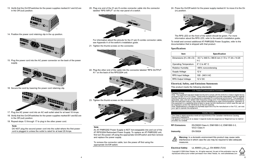
24.Press the On/Off switch for the power supply marked A1 to move it to the On (in) position.
![]() ON
ON
![]() OFF
OFF
RPS |
|
|
12VOUTPUT | A1 | A1 |
DC | ON | |
|
| OFF |
194
14. Position the power cord retaining clip in the up position.
PS |
|
OUTPUT | A2 |
12VDC |
AC |
|
|
|
|
INPUT | A2/A1 | |||
100 | - | 240 |
| |
|
|
| VAC ~ | |
RPS | OUTPUT |
| A1 |
|
| A1 | ON | ||
| 12VDC |
| ||
|
|
|
| OFF |
15.Plug the power cord into the AC power connector on the back of the power supply.
PS |
|
OUTPUT | A2 |
12VDC |
100 | - | 240 | A2/A1 |
|
|
| VAC ~ |
RPS | OUTPUT |
| A1 |
|
| A1 | ON | ||
| 12VDC |
| ||
|
|
|
| OFF |
16. Secure the cord by lowering the power cord retaining clip.
PS |
|
OUTPUT | A2 |
12VDC |
RPS INPUT
400
For information about the pinouts for the
21. Tighten the thumb screws on the connector.
RPS INPUT
401
22.Plug the other end of the cable into the connector labeled “RPS OUTPUT A1” on the back of the RPS3204 unit.
![]() ON
ON
OFF
![]() A2
A2
OUTPUT | A2 |
12VDC |
AC |
|
|
|
|
INPUT | A2/A1 | |||
100 | - | 240 |
| |
|
|
| VAC ~ | |
RPS | OUTPUT |
| A1 |
| A1 | ||
| 12VDC |
|
23. Tighten the thumb screws on the connector.
A2
RPS | OUTPUT |
|
| A2 | |
| 12VDC |
AC |
|
|
|
|
INPUT | A2/A1 | |||
100 | - | 240 |
| |
|
|
| VAC ~ | |
RPS | OUTPUT |
| A1 |
|
| A1 | ON | ||
| 12VDC |
| ||
|
|
|
| OFF |
The RPS LED on the front of the switch should be green. For more information about the RPS LED, refer to the switch’s installation guide.
To install and connect additional
Specifications
Item | Specification |
|
|
|
|
Dimensions (H x W x D) | 43.7 x 440.5 x 360.6 mm (1.72 x 17.34 x 14.20 |
| in.) |
|
|
Operating Temperature | 0° C to 40° C |
|
|
Relative Humidity | <85% noncondensing |
|
|
Supply Voltage | 12 V |
|
|
RPS Input Voltage | 100 - 240 V AC |
|
|
RPS Output Voltage | 12 V DC |
|
|
Electrical, Safety, and Emissions Statements
This product meets the following standards:
U.S. Federal Communications Commission
Radiated Energy
Note: This equipment has been tested and found to comply with the limits for a Class A digital device pursuant to Part 15 of FCC Rules. These limits are designed to provide reasonable protection against harmful interference when the equipment is operated in a commercial environment. This equipment generates, uses, and can radiate radio frequency energy and, if not installed and used in accordance with this instruction manual, may cause harmful interference to radio communications. Operation of
AC |
|
|
|
|
INPUT | A2/A1 | |||
100 | - | 240 |
| |
| VAC ~ | |||
|
|
| ||
RPS | OUTPU | T |
| A1 |
| |
|
|
| ||||
| 12VD | C | A1 | ON | ||
|
|
|
|
|
| OFF |
17.Plug the AC power cord into an AC wall outlet rated for at least 10 Amps.
18.Verify that the On/Off switches for the power supplies marked B1 and B2 are in the Off (out) position.
19.Repeat steps 13 through 17 to plug in the other power cord.
![]() ON
ON
![]() OFF
OFF
![]() A2
A2
RPS | OUTPUT |
|
| A2 | |
| 12VDC |
AC |
|
|
|
INPUT | A2/A1 | ||
100 | - 240 |
| |
|
| VAC ~ | |
RPS | OUTPUT |
|
| A1 | |
| 12VDC |
A1 | ON |
| OFF |
199 |
|
this equipment in a residential area is likely to cause harmful interference in which case the user will be required to correct the interference at his own expense.
Note: Modifications or changes not expressly approved of by the manufacturer or the FCC, can void your right to operate this equipment.
Industry Canada
This Class A digital apparatus meets all requirements of the Canadian
Cet appareil numérique de la classe A respecte toutes les exigences du Règlement sur le matériel brouilleur du Canada.
Note
DO NOT plug the second power cord into the outlet where the first power cord is plugged in unless the outlet is rated for at least 20 Amps.
Note
An
To remove the connector cable, turn the power off first using the appropriate On/Off switch.
RFI Emissions | EN 55022 Class A, |
| VCCI Class A |
Immunity | EN 55024 |
Warning: In a domestic environment this product may cause radio interference in which case the use may be required to take adequate measures.
Electrical Safety UL 60950 (CULUS), EN 60950 (TUV)
Copyright © 2008 Allied Telesis, Inc. All rights reserved. No part of this publication may be reproduced without prior written permission from Allied Telesis, Inc. www.alliedtelesis.com.
4 | 5 | 6 |